Rockwell Automation 20C PowerFlex 700H Drives Programming User Manual
Page 51
Rockwell Automation Publication 20C-PM001F-EN-P - March 2012
51
Programming and Parameters
Chapter 2
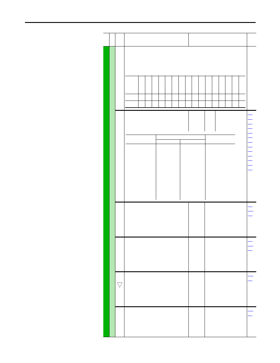
INPUT
S/OUTPUT
S
An
al
og O
u
tpu
ts
341 [Anlg Out Absolut]
Selects whether the signed value or absolute value of a parameter is used before being scaled to
drive the analog output.
1 = Absolute
0 = Signed
342
345
[Analog Out1 Sel]
[Analog Out2 Sel]
Selects the source of the value that drives the
analog output.
Default:
Options:
0
–>
“Output Freq”
(See table below)
001
002
003
004
005
007
006
012
135
136
137
138
220
343
346
[Analog Out1 Hi]
[Analog Out2 Hi]
Sets the analog output value when the source
value is at maximum.
Note: The Min. value was changed from
4.000 mA…0.000 mA for firmware revision
3.001.
Default:
Min/Max:
Units:
20.000 mA, 10.000 Volts
0.000/20.000 mA
–/+10.000V
0.000/10.000V
0.001 mA
0.001 Volt
340
342
345
344
347
[Analog Out1 Lo]
[Analog Out2 Lo]
Sets the analog output value when the source
value is at minimum.
Note: The Min. value was changed from
4.000 mA…0.000 mA for firmware revision
3.001.
Default:
Min/Max:
Units:
0.000 mA, 0.000 Volts
0.000/20.000 mA
–/+10.000V
0.000/10.000V
0.001 mA
0.001 Volt
340
342
345
354
355
[Anlg Out1 Scale]
[Anlg Out2 Scale]
Sets the high value for the range of analog output
scale. Entering 0.0 will disable this scale and max
scale will be used. Example: If [Analog Outx Sel]
= “Commanded Freq,” a value of 150 = 150%
scale in place of the default 200%.
Default:
Min/Max:
Units:
0.0
[Analog Outx Sel]
0.1
342
345
377
378
[Anlg1 Out Setpt]
[Anlg2 Out Setpt]
Sets the analog output value from a
communication device. Example: Set [Data In Ax]
to “377” (value from communication device).
Then set [Analog Outx Sel] to “Param Cntl.”
Default:
Min/Max:
Units:
0.000 mA, 0.000 Volts
0.000/20.000 mA
–/+10.000V
0.001 mA
0.001 Volt
342
345
Fil
e
Gr
oup
No
.
Parameter Name & Description
Values
Rela
ted
Name
Re
se
rv
ed
Re
se
rv
ed
Re
se
rv
ed
Re
se
rv
ed
Re
se
rv
ed
Re
se
rv
ed
Re
se
rv
ed
Re
se
rv
ed
Re
se
rv
ed
Re
se
rv
ed
Re
se
rv
ed
Re
se
rv
ed
Re
se
rv
ed
Re
se
rv
ed
Analog Out2
Analog Out1
Default
x
x
x
x
x
x
x
x
x
x
x
x
x
x
1
1
Bit
15
14
13
12
11
10
9
8
7
6
5
4
3
2
1
0
Options
[Analog Outx Lo] Value
[Analog Outx Hi] Value
Par 341 = Signed
Par 341 = Absolute
0
1
2
3
4
5
6
7
8
9
10
11
12
13…15
16
17…23
24
“Output Freq”
“Command Freq”
“Output Amps”
“Torque Amps”
“Flux Amps”
“Output Power”
“Output Volts”
“DC Bus Volt”
“PI Reference”
“PI Feedback”
“PI Error”
“PI Output”
“%Motor OL”
“Reserved”
“Speed Ref”
“Reserved”
“Param Cntl”
–[Maximum Speed]
–[Maximum Speed]
0 Amps
–200% Rated
0 Amps
0 kW
0 Volts
0 Volts
–100%
–100%
–100%
–100%
0%
–
–[Maximum Speed]
–
0 Hz
0 Hz/RPM
0 Amps
0 Amps
0 Amps
0 kW
0 Volts
0 Volts
0%
0%
0%
0%
0%
–
0 Hz
–
+[Maximum Speed]
+[Maximum Speed]
200% Rated
200% Rated
200% Rated
200% Rated
120% Rated Input Volts
200% Rated Input Volts
100%
100%
100%
100%
100%
–
+[Maximum Speed]
–
32