Rockwell Automation 20C PowerFlex 700H Drives Programming User Manual
Page 65
Rockwell Automation Publication 20C-PM001F-EN-P - March 2012
65
Troubleshooting
Chapter 3
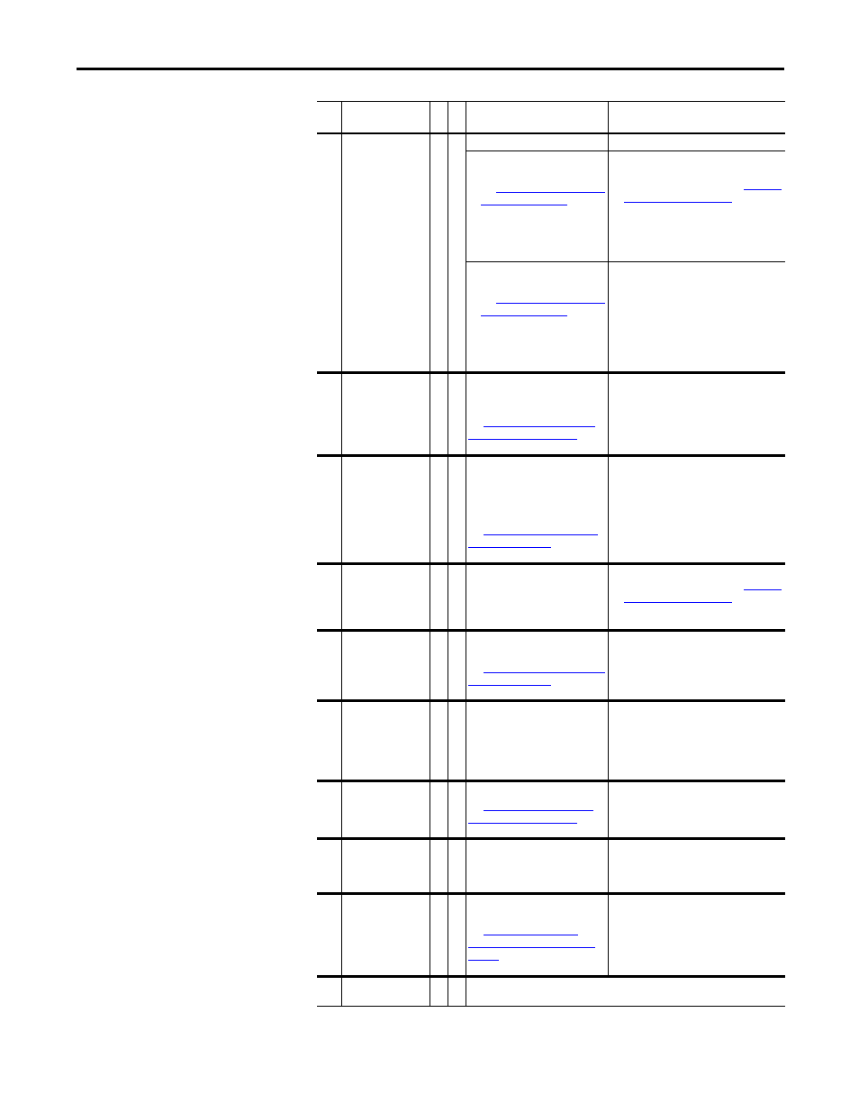
10
System Fault
2
One of the following has occurred:
• A hardware problem exists in
the power structure.
See
information on this fault.
Note: Subcodes are only
available in revision 4.001 or
later.
1. Cycle the power.
2. Verify the fiber optic connections.
3. Contact Technical Support. See
for more
information. If the problem persists,
replace the drive.
• The 20C-DG1 option board has
been removed.
See
information on this fault.
Note: Subcodes are only
available in revision 4.001 or
later.
Set parameter 358 [20C-DG1 Remove] to
1"Remove” and then back to 0 “Ready” to
clear and acknowledge the fault. Once
maintenance or service is completed and the
20C-DG1 option card has been reinstalled,
the drive will recognize the option card on
power-up.
12
OverCurrent
1
The drive output current has
instantaneously exceeded 360% of
the HD rating.
See
for
more information on this fault.
Check programming for an excess load,
improper DC boost setting, DC brake voltage
set too high or other causes of excess
current. Check for shorted motor leads or a
shorted motor.
13
Ground Fault
1
A current path to earth ground
exists that is greater than 50% of
the drive's heavy duty rating. The
current must appear for 800ms
before the drive will fault.
See
for more
information on this fault.
Check the motor and external wiring to the
drive output terminals for a grounded
condition.
14
InverterFault
2
A hardware problem exists in the
power structure.
1. Cycle the power.
2. Contact Technical Support. See
for more
information.
3. If the problem persists, replace the drive.
15
Load Loss
3
1 Do not use this fault in PowerFlex
700H applications.
See
Table 12, “Load Loss Fault (F15)
for more
information on this fault.
Parameter 238 [Fault Config 1] / bit 0
“Power Loss” and parameter 259 [Alarm
Config 1] / bit 13 “Load Loss” are set to zero.
16
Motor Therm
3
1 The option board thermistor input
is greater than the limit.
1. Check to ensure that the motor is cooling
properly.
2. Check for an excess load.
3. Verify the thermistor connection. If the
thermistor connection on the option
board is not used, it must be shorted.
17
Input Phase
3
1 One input line phase is missing.
See
for
more information on this fault.
1. Check all user-supplied fuses
2. Check the AC input line voltage.
19
Unbalanced
2
An imbalance between the power
modules exists (paralleled units -
frames 12 & 14 only).
1. Check for DC voltage imbalance between
the power modules.
2. Check for current output imbalance
between the power modules.
21
OutPhasMissng
2
There is zero current in one of the
output motor phases.
See
Missing Fault (F21) Subcode,” on
page 74
for more information on
this fault.
1. Check the motor wiring.
2. Check the motor for an open phase.
22
NP Hz Cnflct
2 The “fan/pump” mode is selected in [Motor Cntl Sel] and the ratio of parameter 43
[Motor NP Hertz] to 55 [Maximum Freq] is greater than 26.
No. Name
Fa
u
lt
Alarm
Description
Action (if applicable)