Rockwell Automation 20C PowerFlex 700H Drives Programming User Manual
Page 66
66
Rockwell Automation Publication 20C-PM001F-EN-P - March 2012
Chapter 3
Troubleshooting
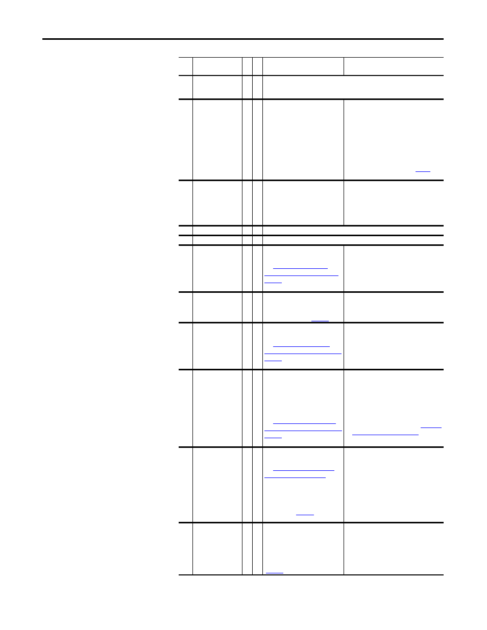
23
MaxFreqCnflct
2 The sum of parameters 82 [Maximum Speed] and 83 [Overspeed Limit] exceeds
55 [Maximum Freq]. Raise [Maximum Freq] or lower [Maximum Speed] and/or
[Overspeed Limit] so that the sum is less than or equal to [Maximum Freq].
24
Decel Inhibit
3
1 The drive cannot follow the
commanded decel due to bus
limiting.
1. Verify that the input voltage is within the
specified limits.
2. Verify that the system ground impedance
follows the proper grounding
techniques.
3. Disable bus regulation and/or add a
dynamic brake resistor and/or extend the
deceleration time. Refer to the Attention
statement regarding the “adjust freq”
setting for bus regulation on
for
more information.
25
OverSpd Limit
1
Functions such as Slip
Compensation or Bus Regulation
have attempted to add an output
frequency adjustment greater than
the value programmed in
parameter 83 [Overspeed Limit].
Remove the excessive load or overhauling
conditions or increase the value in
[Overspeed Limit].
26
VHz Neg Slope
2 Parameter 53 [Motor Cntl Sel] = “Custom V/Hz” & the V/Hz slope is negative.
27
SpdRef Cnflct
2 [Speed Ref x Sel] or [PI Reference Sel] is set to “Reserved”.
28
BrakResMissing
2
No brake resistor has been
detected.
See
Missing Fault (F28) Subcodes,” on
page 74
for more information on
this fault.
1. Program [Bus Reg Mode x] to not use the
brake option.
2. Install a brake resistor and set parameter
163 [DB Resistor Type] to 1 “External Res”
(frame 9 drives only).
29
Anlg In Loss
1,
3
1 An analog input is configured to
fault on a signal loss. A signal loss
has occurred. Configure this fault
with [Anlg In x Loss] (
).
1. Check parameter settings.
2. Check for broken/loose connections at
the inputs.
30
MicroWatchdog
2
A microprocessor watchdog
timeout has occurred.
See
Watchdog Fault (F30) Subcode,” on
page 74
for more information on
this fault.
1. Cycle the power.
2. Replace the Main Control board.
31
IGBT Temp HW
2
The drive output current has
exceeded the instantaneous current
limit.
Note: IGBT Temp HW = Drive
Instantaneous Overload
(Hardware), not adjustable.
See
Hardware Fault (F31) Subcodes,” on
page 74
for more information on
this fault.
1. Check for an excess load.
2. Raise the value set in either [Accel Time
x] parameters.
3. Parameter 53 [Motor Cntl Sel] may need
to be set to “Custom V/Hz”.
4. Verify the values set in parameters 62 [IR
Voltage Drop] and 63 [Flux Current Ref].
5. Contact Technical Support. See
for more
information.
32
Fan Cooling
2
2 Fan is not energized at start
command.
See
for
more information on this fault.
You can configure this fault to be an
alarm by setting bit 14 “Fan
Cooling” of parameter 238 [Fault
Config 1] to 1 (
1. Check for flashing LEDs on the fan
inverter board(s).
2. Check the fan motor bearings.
3. Check the fan motor windings resistance.
4. Check the fan inverter fuses.
5. Check the 7 μF fan capacitor(s).
Note: See the “PowerFlex 700S and 700H
Drives Hardware Service Manual” for the
applicable frame size for component
locations.
33
AutoReset Lim
3
The drive unsuccessfully attempted
to reset a fault and resumed
running for the programmed
number of [Auto Rstrt Tries]. You
can enable/disable this fault with
parameter 238 [Fault Config 1]
(
).
Correct the cause and manually clear the
fault.
No. Name
Fa
u
lt
Alarm
Description
Action (if applicable)