Terminal description, Technical data – Lenze 8400 protec Manual User Manual
Page 59
Technical data
Terminal description
l
59
EDS84DPS424 EN 5.0
4.5
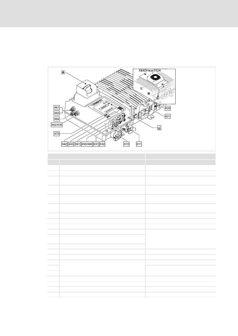
Terminal description
Overview
StateLine, HighLine
E84DWGA010
Operational controls and connections
Pos.
Function
Description
0
Control element
Optional
+
PE connection
for M6 ring cable lug
X10
Mains and 24−V buffer voltage
DESINA Q4/2, pins
Optional: Molex (
^ 87)
X11
Optional: Loop−through technique − mains and 24−V
buffer voltage
DESINA Q4/2, sockets (optional)
Optional: Molex
X20
Optional: For external brake resistor
Q5/0, sockets (optional)
Optional: Molex
X21
Motor, temperature monitoring and motor holding
brake
Q8/0, Modular or 10E, sockets
X31
Fieldbus input
Socket RJ45 or M12, A−coded, male
X32
Fieldbus output
Socket RJ45 or M12, A−coded, female
X35
CAN on board
M12, 5−pole sockets, A−coded
X41
Digital inputs DI1 and DI2
M12, 5−pole sockets, A−coded
X42
Digital inputs DI3 and DI4, also configurable as digital
outputs DO1 and DO2
X43
Digital inputs DI5 and DI6
X50
Analog input AI, AU
M12, 5−pole sockets, A−coded
X61
Safety system, option 10
M12, 5−pole pins, A−coded
X62
Safety system, option 30
M12, 5−pole sockets, A−coded
X63
M12, 8−pole sockets, A−coded
X64
X70
Diagnostics
Socket RJ69
X80
Synchronous serial interface (SSI)
M12, 8−pole sockets, A−coded
;
only E84DHxxx7524: External fan
<
Operating voltage for the external fan
−