Electrical installation − ems version, Control terminals digital inputs and outputs, Example circuit – Lenze 8400 protec Manual User Manual
Page 130
Electrical installation − EMS version
Control terminals
Digital inputs and outputs
l
130
EDS84DPS424 EN 5.0
X48 − digital inputs DI13, DI14
Pin
Signal
Description
Data
84DPSO05_5
Type M12, 5−pole sockets
1
24O
24 V supply of the external sensors
2
DI14
Digital input 14
HIGH
+15 .... +30 V DC
3
GIO
Reference potential
LOW
0 ... +5 V
4
DI13
Digital input 13
8 mA at 24 V DC
5
n. c.
Not assigned
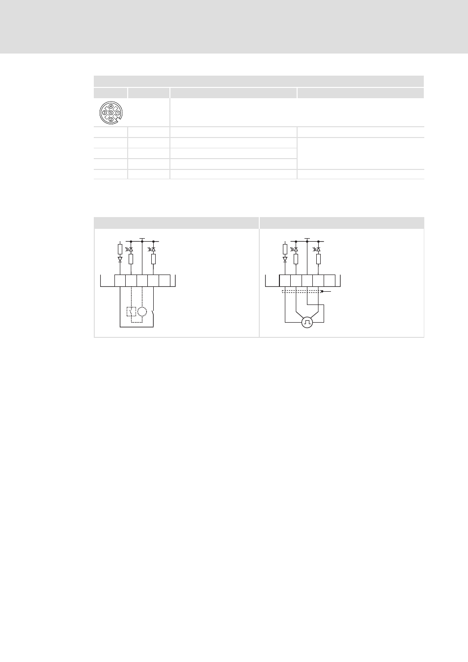
Example circuit
0
1
DI1
S1
X41
GND-IO
GIO
24O
3.3k
3.3k
DI2
S2
=
-
+
DI1
X41
GND-IO
GIO
24O
3
.3k
3
.3k
DI2
"
8400DIO045
8400DIO022
Fig. 7−5
Wiring examples of the digital inputs
0
Wiring of digital inputs, examples:
S1
Potential−free contact, at internal 24 V supply
S2
Signal source, e.g. PLC or with external 24 V supply
1
Connection of an HTL incremental encoder with a maximum input frequency of
100 kHz
DI1
track A
DI2
track B
X41
Plugs for digital inputs X41 ... X43
GIO
Ground reference potential for the digital inputs and outputs (GND−IO)
- p300 Mounting Instructions (12 pages)
- p300 Operating Instructions (37 pages)
- I/O system 1000 System Manual (744 pages)
- CS5800 Mounting Instructions (89 pages)
- CS5800 Operating Instructions (60 pages)
- Controller-based Automation (63 pages)
- Controller-based Automation (68 pages)
- 2121IB LECOM-Li (29 pages)
- HMI for visualisation / with control technology (96 pages)
- Controller 3200 C Operating Instructions (40 pages)
- c300 Operating Instructions (35 pages)
- EL 1800 Mounting Instructions (89 pages)
- EL 1800 Operating Instructions (57 pages)
- 3200 C (38 pages)
- 3200 C (195 pages)
- CPC 2800 Mounting Instructions (59 pages)
- CPC 2800 Operating Instructions (39 pages)
- CS 5000 DVI Mounting Instructions (86 pages)
- CS 5000 DVI Operating Instructions (53 pages)
- MP 800 DVI Mounting Instructions (88 pages)
- MP 800 Operating Instructions (43 pages)
- 8400 motec Manual (121 pages)
- 8400 motec Mounting Instructions (164 pages)
- 9400 Manual (584 pages)
- 9400 Mounting Instructions (208 pages)
- 8400 (1494 pages)
- 8400 (304 pages)
- i700 Manual (159 pages)
- 8400 BaseLine Manual (114 pages)
- 8400 BaseLine Guide Quick Guide (10 pages)
- EZAEDE1000 (76 pages)
- EMF2180IB EthernetCAN (134 pages)
- EMF2181IB (154 pages)
- EMF2181IB (83 pages)
- EMF2177IB (28 pages)
- EMF2177IB (18 pages)
- E84AZESR RFI filter 3-29A (154 pages)
- E84AZESM Mains filter-RFI filter 42-96A (120 pages)
- ESVZAR0 RS-485 (33 pages)
- ESV SMV frequency inverter (66 pages)
- CANopen Controller-based Automation (110 pages)
- PROFIBUS Controller-based Automation (55 pages)
- EtherCAT Controller-based Automation (205 pages)
- PROFINET Controller-based Automation (44 pages)