Electrical installation − ems version, Stop – Lenze 8400 protec Manual User Manual
Page 125
Electrical installation − EMS version
Devices in a power range of 0.75 ... 4 kW (3/PE AC 400 V)
Terminal assignment of the power connections
l
125
EDS84DPS424 EN 5.0
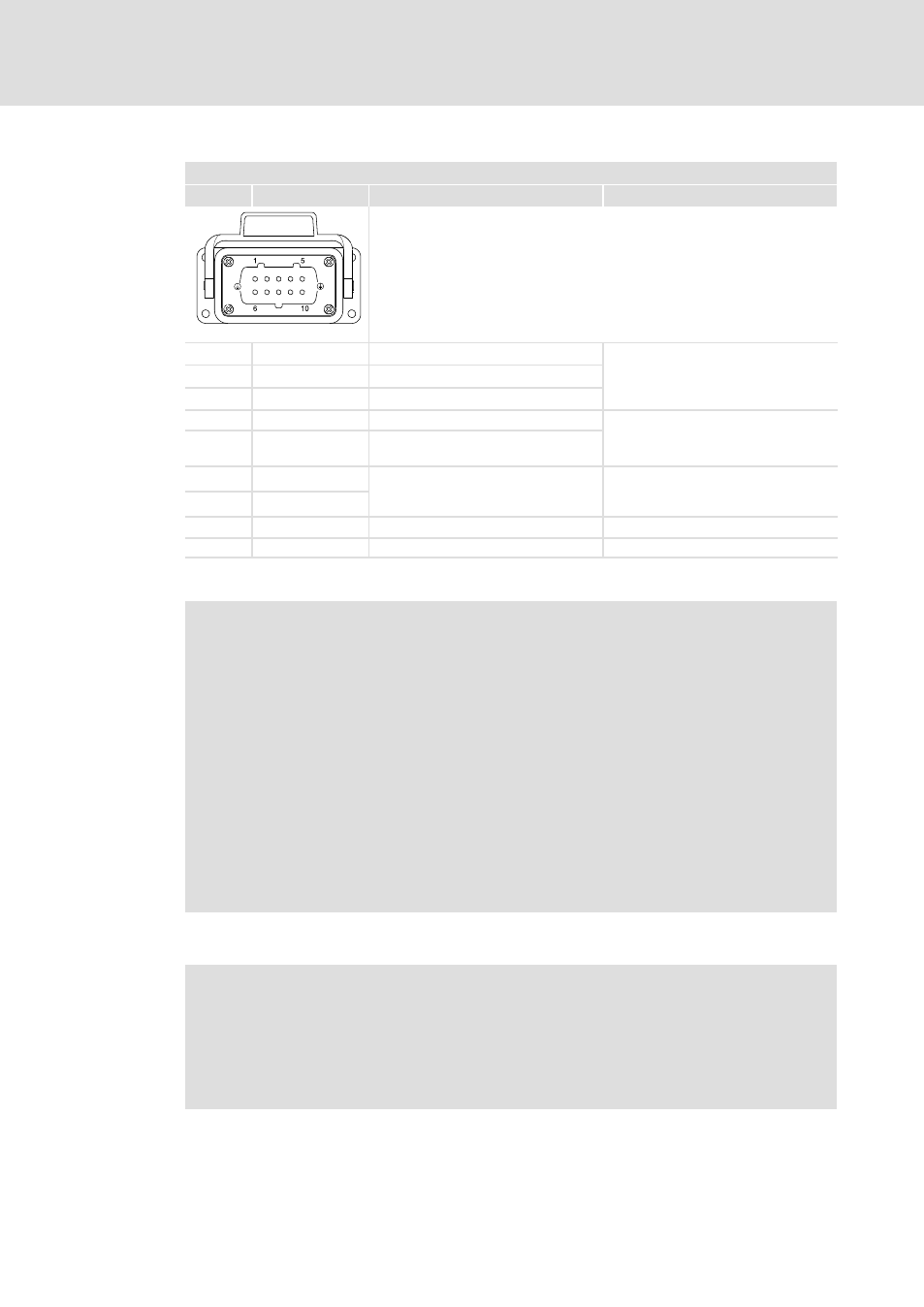
X21 − motor connection − device version E84DxH...
Pin
Connection
Description
Data
Type Han 10E, sockets
84DWTX0212
1
U
Motor phase U
Max. 4 mm
2
Max. output voltage: mains voltage
Max. permanent output current:
type−dependent
2
V
Motor phase W
3
W
Motor phase V
4
BD1
Motor holding brake
Max. 4 mm
2
9
BD2
Motor holding brake (reference
conductor)
5
+PTC
Motor temperature monitoring
Max. 4 mm
2
PTC thermistor (PTC) or thermal
contact (NC contact)
10
−PTC
6, 7, 8
n. c.
−
−
+
PE
PE conductor
Max. 4 mm
2
, above housing
(
Stop!
Damage of the devices
A defective motor holding brake or a short circuit on the X21 connection
(motor and built−on accessories) causes internal damage to the device.
Possible consequences:
ƒ
If a defective motor holding brake is connected, the replacement device is
also damaged immediately.
Protective measures:
ƒ
When devices are replaced due to malfunction of the brake control, ensure
that defect−free motor holding brakes are connected.
ƒ
Check whether the motor holding brake and the connecting cable are free
from defects.
ƒ
Replace or repair defective components.
)
Note!
In the Lenze setting, the temperature monitoring of the motor is activated! To
start motors without thermal detectors, the response of the motor
temperature monitoring must be deactivated (C00585). Alternatively, a wire
jumper between +PTC and −PTC can be used to simulate a normal
temperature.