5 system architecture, System architecture, 5system architecture – Lenze Controller-based Automation User Manual
Page 47
Lenze · Controller-based Automation · System Manual · DMS 1.4 EN · 04/2014 · TD17
47
5
System architecture
5.1
Communication link between Engineering PC and field devices
_ _ _ _ _ _ _ _ _ _ _ _ _ _ _ _ _ _ _ _ _ _ _ _ _ _ _ _ _ _ _ _ _ _ _ _ _ _ _ _ _ _ _ _ _ _ _ _ _ _ _ _ _ _ _ _ _ _ _ _ _ _ _ _
5
System architecture
By means of the Engineering PC, you commission one or several Controllers.
For this purpose, install
required for commissioning, parameter setting,
configuration and diagnostics of the Lenze automation system on the Engineering PC.
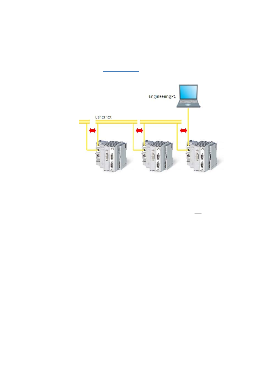
[5-1]
Example: Engineering PC with several 3200 C controllers, connected via integrated Ethernet switch
• The Controllers 3200 C/p500 are equipped with an integrated Ethernet switch, which enables a
line topology.
• Connection of the Engineering PC is only required for programming and commissioning.
Continuous operation of the control and visualisation system does not require the Engineering
PC anymore afterwards.
• The Engineering PC is connected to the respective controller via the network interface and
communicates via Ethernet.
5.1
Communication link between Engineering PC and field devices
The Engineering PC is required to commission the controller and for the commissioning of the
inverters as well as of the other subordinate field devices.
In order to establish an online connection between the Engineering PC and a field device (e.g. i700
servo inverter), two communication links are possible:
Online connection via the gateway function of the controller via CAN/EtherCAT