5 bus systems, Bus systems, 4system components – Lenze Controller-based Automation User Manual
Page 39
Lenze · Controller-based Automation · System Manual · DMS 1.4 EN · 04/2014 · TD17
39
4
System components
4.5
Bus systems
_ _ _ _ _ _ _ _ _ _ _ _ _ _ _ _ _ _ _ _ _ _ _ _ _ _ _ _ _ _ _ _ _ _ _ _ _ _ _ _ _ _ _ _ _ _ _ _ _ _ _ _ _ _ _ _ _ _ _ _ _ _ _ _
4.5
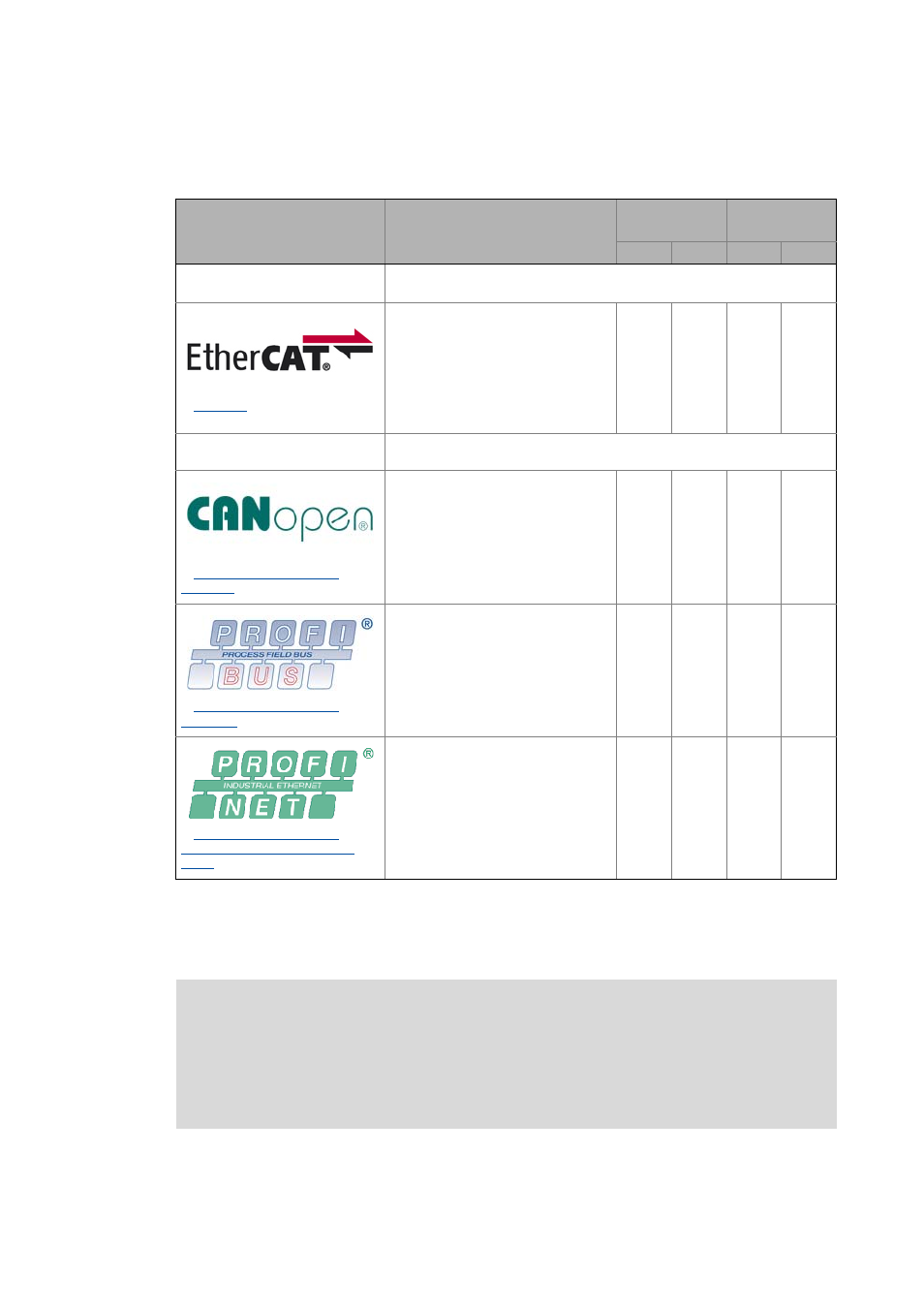
Bus systems
Depending on the bus system used...
• the basic structure of the network varies.
• various Lenze device series can be used.
Bus system
Description
Connection
Runtime
Software
Master Slave
Logic
Motion
Standard topology:
EtherCAT "on board"
The controller (as the central control component) by default communicates
with the subordinate field devices via EtherCAT.
Integrated EtherCAT (on board):
• Real time-capable and
synchronisation-capable system for
every application.
• EtherCAT interface on board
• Standard bus system for the
"Controller-based Automation"
system
-
Extended topologies by optional
communication cards
For specific applications, the "Controller-based Automation" system
additionally supports master/slave connections for the following bus systems:
CANopen (optional):
• Tried-and-tested system for smaller
plants by CANopen profiles.
• Possible with optional MC-CAN2
communication card.
• CANopen interface "on board" for
Controller c300/p300
PROFIBUS (optional):
• For the greatest selection of
different field devices.
• Possible with optional MC-PBM
communication card (master) or
MC-PBS (slave).
-
PROFINET (optional):
• For the control of field devices via
PROFINET. The Lenze Controller is
integrated as I/O device (slave), for
example under a Siemens SIMATIC
S7 PLC.
• Possible with optional MC-PND
communication card.
-
-
More information on the bus systems and configuration can be found in the
communication manuals:
• Controller-based Automation EtherCAT®
• Controller-based Automation CANopen®
• Controller-based Automation PROFIBUS®
• Controller-based Automation PROFINET®