1 ethercat, Ethercat, Ethercat ( 40) – Lenze Controller-based Automation User Manual
Page 40: 4system components
4
System components
4.5
Bus systems
40
Lenze · Controller-based Automation · System Manual · DMS 1.4 EN · 04/2014 · TD17
_ _ _ _ _ _ _ _ _ _ _ _ _ _ _ _ _ _ _ _ _ _ _ _ _ _ _ _ _ _ _ _ _ _ _ _ _ _ _ _ _ _ _ _ _ _ _ _ _ _ _ _ _ _ _ _ _ _ _ _ _ _ _ _
4.5.1
EtherCAT
Physical structure
Due to the installed synchronisation mechanisms via "Distributed Clocks", EtherCAT offers excellent
real-time features.
• The high performance of EtherCAT makes it possible to control all field devices on one common
bus (e.g. by inverters with a Logic/Motion function).
• EtherCAT provides for a greater number of field devices that can be controlled simultaneously
and a greater maximum bus length than the CANopen bus system.
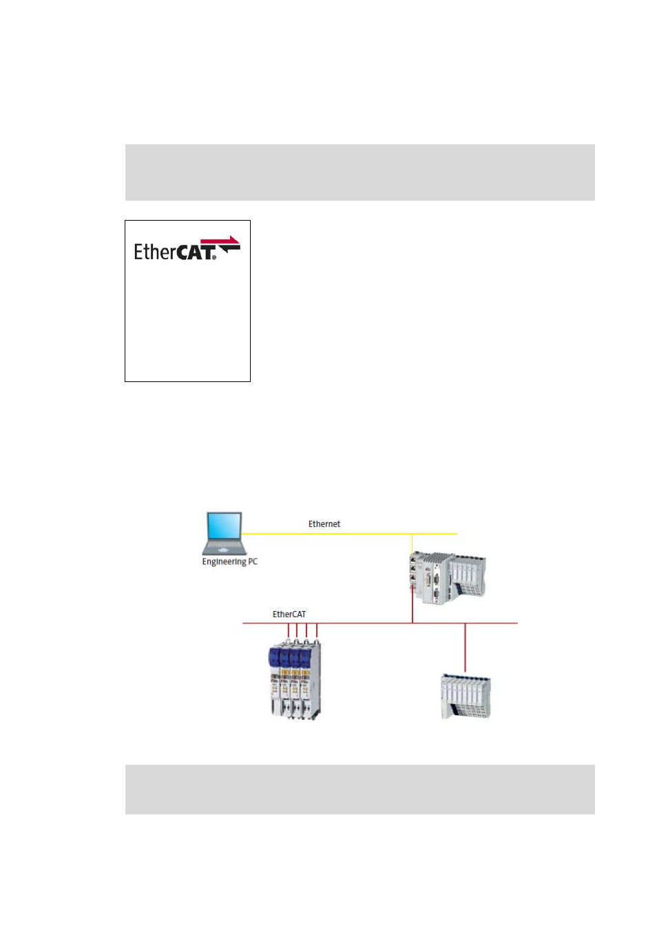
[4-4]
Example configuration (EtherCAT bus system): 3200 C Controller with I/O system 1000 and i700 servo inverter
Note!
For the Controller c300/p300, the EtherCAT communication is currently being prepared.
EtherCAT is an Ethernet-based bus system which provides for Logic
and Motion functions on one common fieldbus.
• According to the EtherCAT specification, (theoretically) up to
65535 nodes can be connected to an EtherCAT line. In practical
applications, the maximum number of nodes mainly depends on
the performance of the controller used. Depending on the
required computing time and the applications of the controller
(PLC and optional visualisation), a great number of nodes at a low
cycle time (1 ms) can be implemented.
• Lenze Controllers are equipped with an integrated EtherCAT
communication interface (on board).
Communication manual "Controller-based Automation EtherCAT®"
Here, further information on the bus system and configuration can be found.