6 configuration, 1 selectors, 1 analog selector – JUMO 705001 mTRON T - Central Processing Unit Operating Manual User Manual
Page 51: Configuration, Selectors
51
6 Configuration
6.1
Selectors
The selectors contain all analog and digital signals that are available for configuration in the
central processing unit.
These are, firstly, the central processing unit (CPU) signals. This relates to internal signals (incl.
PLC) and variables. The values of the variables are read in via an interface, such as Com1.
Chapter 6.3 "Variables", page 60
Chapter 8.2 "Modbus frames for reading", page 114
Secondly, they are signals originating from the input/output modules (incl. multichannel control-
ler module) and multifunction panel.
6.1.1
Analog selector
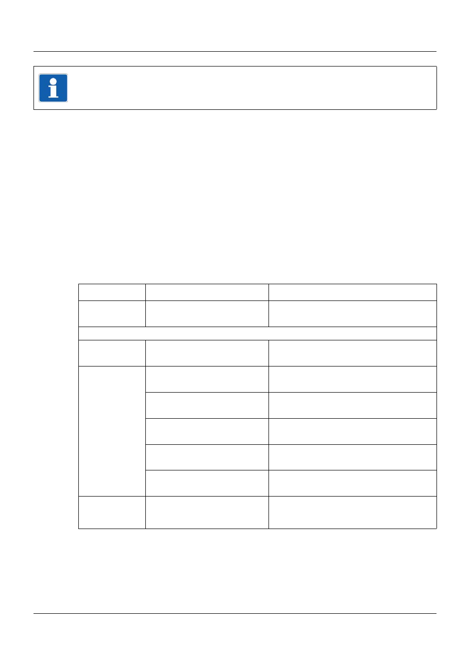
The following table lists all analog signals.
NOTE!
The parameters described in this section can be configured either with the setup program, or
on the multifunction panel (exception: setup info in the device data).
Category
Signal
Description
Inactive
No signal selected
Central processing unit
Analog variables
Analog variable 1 to 64
Analog variable 1 to 64 (via interface)
Program
generator 1 to
Program
generator 9
Channel 1 SP1 to Channel 3 SP1 Setpoint value 1 of program channel 1 to 3
Channel 1 SP2 to Channel 3 SP2 Setpoint value 2 of program channel 1 to 3
Channel 1 SP2 to Channel 3 SP2 Setpoint value 3 of program channel 1 to 3
Channel 1 SP4 to Channel 3 SP4 Setpoint value 4 of program channel 1 to 3
PLC Analog output 13 to 16
Signal of PLC analog output 13 to 16
Analog PLC out-
put block 10 to
block 18
PLC Analog output 1 to 16
Signal of PLC analog output 1 to 16