2 description, 1 brief description, 2 block diagram – JUMO 705001 mTRON T - Central Processing Unit Operating Manual User Manual
Page 17: Description, Brief description, Block diagram
17
2 Description
2.1
Brief description
The central processing unit is the heart of the system. It contains the process image of the ap-
plication and manages the configuration and parameter data of the complete system (except
for the multifunction panel).
For individual control tasks nine program generators (option) are available and 64 limit values
can be monitored.
LEDs are used to indicate applied voltage supply, the operating status of the PLC, system mal-
functions, as well as the communication through interfaces.
A USB device interface (setup), a LAN connection (Ethernet), and two system bus connections
are available as standard. Up to two interfaces can be optionally equipped for fieldbus applica-
tions.
The central processing unit, the input/output modules connected laterally, and modules inte-
grated by a router are comfortably configured and parameterized with the setup program.
A PLC according to IEC 61131-3 can be released as an option. A switch is available to toggle
the system operating status (Run, Stop, and Reset).
2.2
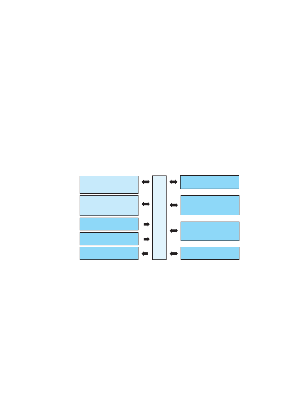
Block diagram
Com1
RS232 (Modbus RTU) or
RS422/485 (Modbus RTU)
705001
Voltage supply Out
System bus
Com2
RS232 (Modbus RTU) or
RS422/485 (Modbus RTU) or
PROFIBUS-DP slave
USB (device)
For setup program
Bus Out
To permit connection to a
multifunction panel or
router module
LAN
Mainly for use of the
integrated web server
or the setup program
Switch / push-button
Run, Stop, or Reset
Voltage supply In
(at the front)