INFICON 3000 Micro GC Gas Analyzer Operating Manual User Manual
Page 84
5 - 10
PN
07
4-
51
9-
P1
C
3000 Micro GC Operating Manual
6
Align the Pressure Reducer bracket horizontally on the face of the
3000 Micro GC so that the end of the outlet tubing is near the inlet fitting.
Place the lower lip of the mounting bracket under the bottom front panel as
shown in
. The edge of the 3000 Micro GC front molding will fit into
the groove in the bracket.
Figure 5-11 Installing the bracket onto the 3000 Micro GC
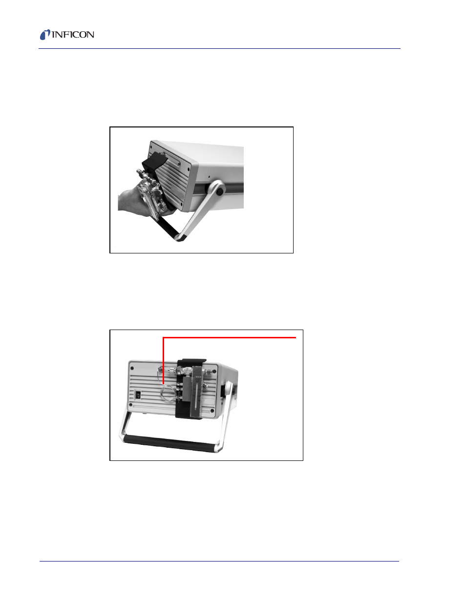
7
While maintaining the alignment of the outlet tubing and the inlet fitting
(or 10 micro sample inlet filter), tilt the bracket up and snap it onto the front of
the 3000 Micro GC. When properly mounted, the bracket should be flat against
the 3000 Micro GC frame. Insert the outlet tubing into the sample inlet fitting (or
10 micron sample inlet filter). See
Figure 5-12 Pressure reducer, installed
8
The sample outlet tubing should insert easily into the 3000 Micro GC inlet
fitting. If not, slide the accessory along the 3000 Micro GC frame until the
sample outlet tubing is unstressed.
9
Tighten the 5/16 in. nut to the sample inlet fitting using the 5/16 in. open-ended
wrench.
PN G2815A on a 2-channel
3000 Micro GC
Outlet tube installed
PN G2815A on a
2-channel
3000 Micro GC