Festo DHTG User Manual
Page 33
DHTG
Festo – DHTG – 1404d English
33
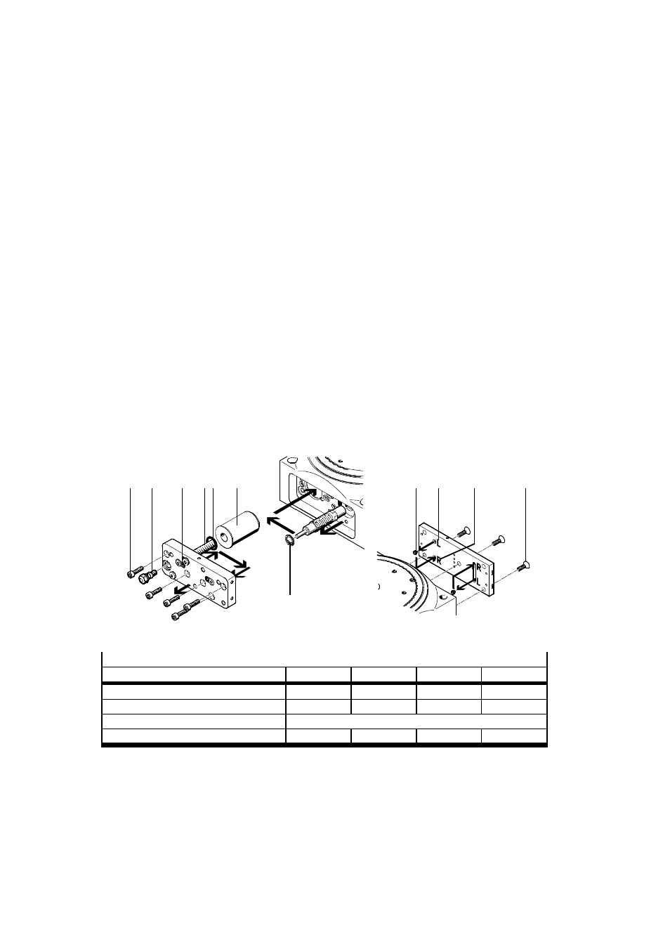
Conversion from clockwise rotation (as supplied) to anti-clockwise rotation:
1. Loosen the clamping element (K) of the adjusting screw one rotation.
2. Unscrew the adjusting screw
6 a few rotations.
3. Unscrew flow control screw
aJ and the fastening screws (M) from the sub-base.
4. Using pliers, remove the retaining ring (S) on the shock absorber.
5. Fit the following:
–
the shock absorber with the retaining ring in the adjacent hole
–
the O-ring (P) / buffer (for DHTG-65) in the adjacent groove
–
the distance piece (T) in the same hole (distance piece omitted for 2/3 index stations)
–
the sub-base with the fastening screws and the flow control screw in reverse sequence
(tightening torque
Tab. 17).
6. Unscrew the fastening screws (N) on the stop plate.
7. Unscrew:
–
both locking screws (O) on the rear of the stop plate to begin with,
–
then screw them in again into the open holes (tightening torque
Tab. 17).
The open holes
(R) or (L) in Fig. 14 determine the direction of rotation
(Holes (R) open: clockwise rotation).
8. Screw the fastening screws (N) on the stop plate again (tightening torque
Tab. 17).
The rotary indexing table remains pneumatically controlled as before.
9. Screw in the adjusting screw
6 until the desired cushioning is achieved
Fig. 11.
10.Tighten the clamping element (K) of the adjusting screw (tightening torque
Tab. 15).
(M) aJ
(N)
(O)
(P)
(K)
(L)
(R)
(T)
(S)
6
Fig. 14
Tightening torque
Size
65
90
140
220
Flow control screw
aJ
[Nm]
1.5
1.5
5.5
5.5
Fastening screws (M)
[Nm]
2.9
2.9
9.9
9.9
Plug screw (O)
[Nm]
0.5
Fastening screws (N)
[Nm]
1.5
2.9
5.9
5.9
Tab. 17