Configuration of the safe inputs, 1 configuration possibilities for the safe inputs – EUCHNER Safety Basic Monitor User Manual
Page 40
40
Subject to reasonable modifications due to technical advances
Id.-No.: 114013
Issue date: 14.11.2011
EUCHNER GmbH + Co. KG
Kohlhammerstraße 16, D-70771 Leinfelden-Echterdingen
Tel. +49/711/7597-0, Fax +49/711/753316
Safety Basic Monitor
Configuration of the safe inputs
7.
Configuration of the safe inputs
The unit is configured and diagnosed using the ASIMON software.
Communication takes place over the USB interface.
7.1
Configuration possibilities for the safe inputs
The safe inputs on the unit can be configured variously:
•
Safe inputs for floating contacts.
Two inputs act together on one sub-device which can serve as the source for
a safety device. Test pulses are used to check the inputs for cross-wire short.
•
Safe inputs for self-testing OSSDs (only on contacts S5-S8).
Two inputs act together on one sub-device which can serve as the source for
a safety device. The unit does not check the inputs for cross-wire short, since
this is done by the OSSDs themselves.
•
Standard inputs.
Each channel operates independently. The values can be used like the famil-
iar monitor inputs.
•
Diagnostics outputs.
The test pulse outputs of the input terminals (i.e. terminals S11, S22, S31,
S42, S51, S62, S71, S82) can be used as diagnostics outputs (approx. 10mA
max. output current). A safety device can be assigned to each input, where
the status of the device is represented on the diagnostics output. The diag-
nostics output turns on when the device is “green”.
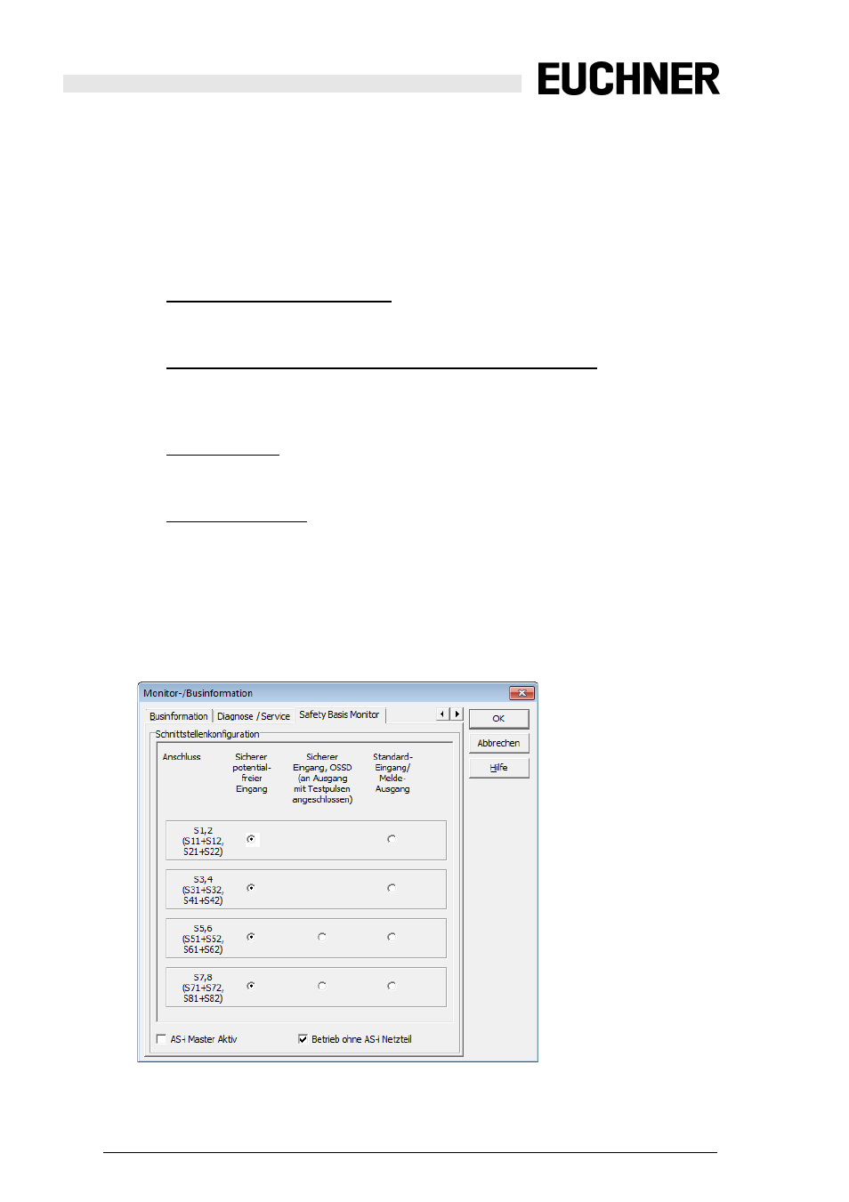
Configuration is done in ASIMON, in the ‘Monitor/Bus Information’ window using
the ‘Safety Basis Monitor’ tab.
The ASIMON Control logic prevents invalid combinations.