EUCHNER Safety Basic Monitor User Manual
Page 25
Subject to reasonable modifications due to technical advances
Id.-No.: 114013
Issue date: 14.11.2011
EUCHNER GmbH + Co. KG
25
Kohlhammerstraße 16, D-70771 Leinfelden-Echterdingen
Tel. +49/711/7597-0, Fax +49/711/753316
Safety Basic Monitor
AS-i Diagnostics
6.3
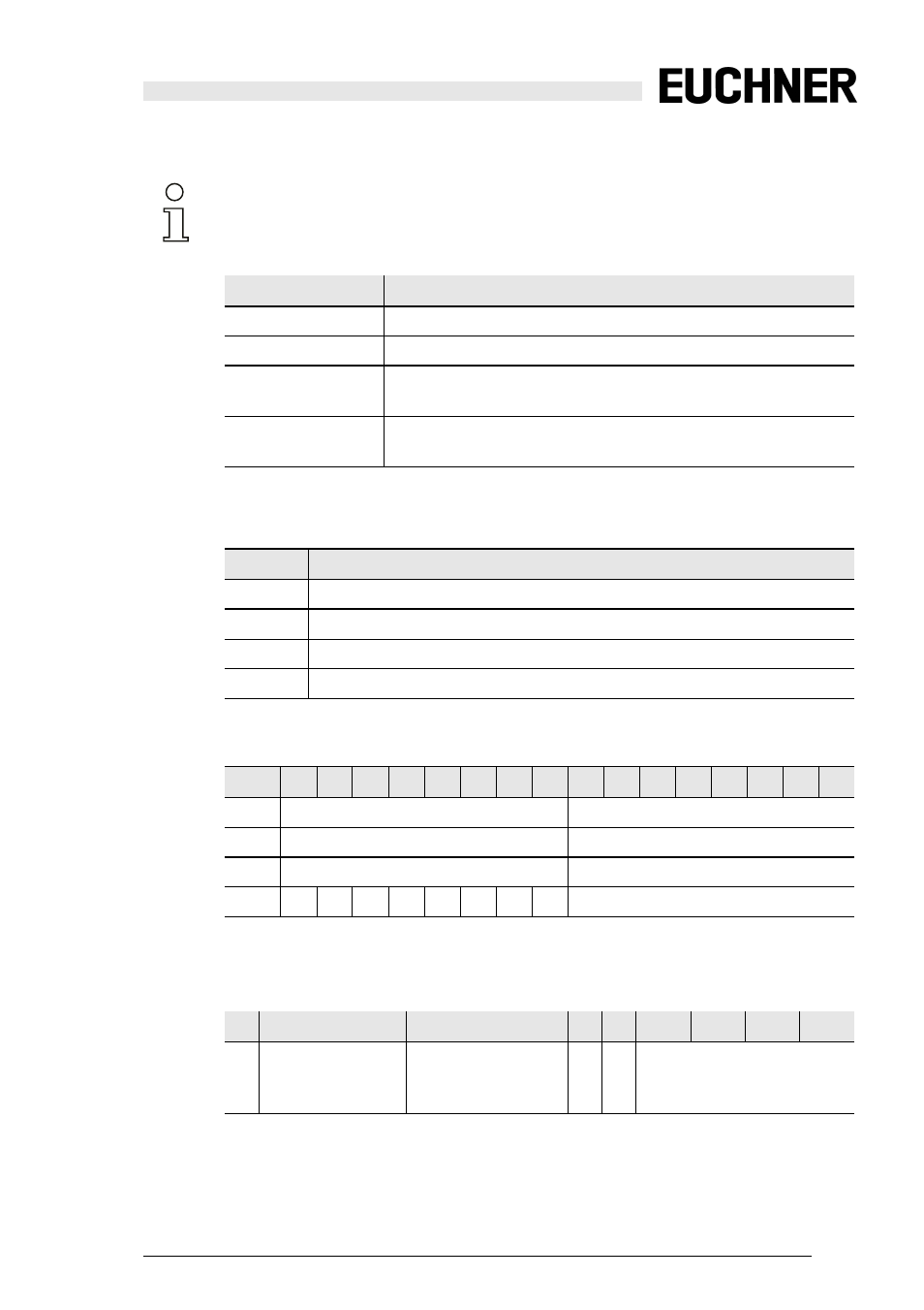
Diagnostics mode "Compatibility mode with additional diagnostics data"
When switch S1 … S8 is closed a ‘1’ is entered in the corresponding position.
The Safety Status is defined as follows:
Information!
Diagnostics type: compatibility mode for Safety Basic Monitors starting with the Safety-
Version ’SV4.3’.
Address
Meanining
basic address
Consortial diagnostics, limited to 48 devices
simulated slave 1
status OSSD 1 and OSSD 2
simulated slave 2
S-7.3 OSSD diagnostics, 4 channel transparent input,
Profil S-7.3.0.C
simulated slave 3
S-7.3 SaW slave diagnostics, 4 channel transparent input,
profile 7.3.1.C
Tab. 6-10.
Simulated slave 1: status OSSD 1 and OSSD 2 (binary data)
Data bit
content
D0
status relay output 1
D1
status message output 1
D2
status relay output 2
D3
status message output 2
Tab. 6-11.
Simulated slave 2 (7.3.0.C): OSSD diagnostics
15
14
13 12
11
10 9
8
7
6
5
4
3
2
1
0
CH1
Safety status OSSD 2
Safety status OSSD 1
CH2
Safety status OSSD 4
Safety status OSSD 3
CH3
Safety status OSSD 6
Safety status OSSD 5
CH4
S8
S7
S6
S5
S4
S3
S2
S1
Safety status OSSD 7
Tab. 6-12.
Bit 7
6
5
4
3
2
1
0
1: not less than
one device red
flashing
1: not less than one
device yellow flash-
ing
n/a n/a OSSD color
(siehe Tab. Status codes for the
release circuits (OSSD))
Tab. 6-13.