1 binary data, 2 transparent input data, Diagnostics mode "as-i 3.0 (s-7.5.5), recommended – EUCHNER Safety Basic Monitor User Manual
Page 27: Binary data, Transparent input data
Subject to reasonable modifications due to technical advances
Id.-No.: 114013
Issue date: 14.11.2011
EUCHNER GmbH + Co. KG
27
Kohlhammerstraße 16, D-70771 Leinfelden-Echterdingen
Tel. +49/711/7597-0, Fax +49/711/753316
Safety Basic Monitor
AS-i Diagnostics
6.4
Diagnostics mode "AS-i 3.0 (S-7.5.5), recommended"
6.4.1
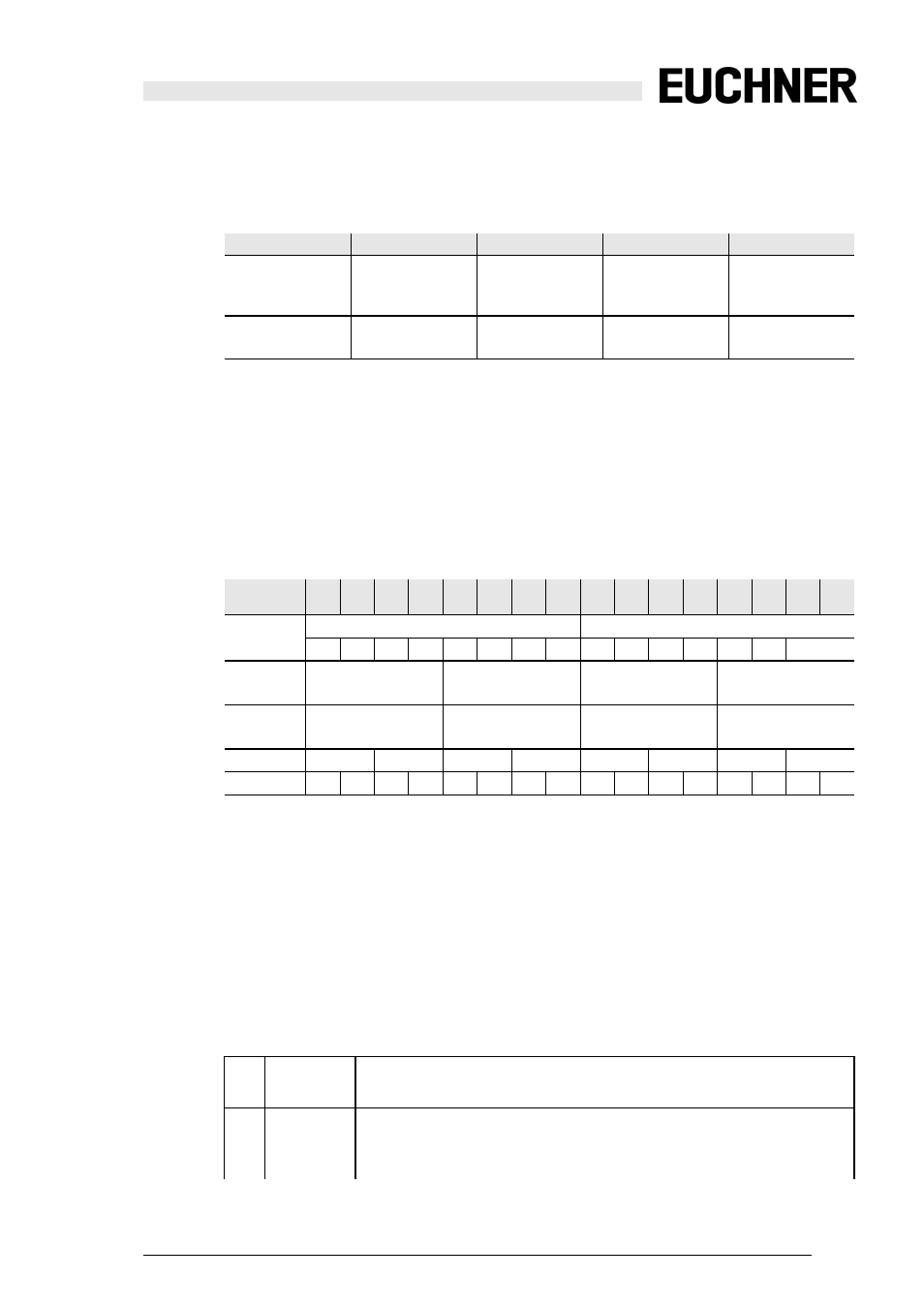
Binary data
6.4.2
Transparent input data
Using profile 7.5.5 it is possible to poll the status of the release circuits (OSSD
Safety Control Status) of the Safety Monitor cyclically (see table below). To do this
you must assign an AS-i address (basic address) to the Safety Monitor and as-
sign an 8-byte analog input slave to the basic address of the Safety Monitor.
These 8 bytes contain the diagnostics data (transparent input data) as shown in
the following table:
Channel ‘0’ of the transparent input data describes the status of the two AS-i seg-
ments. The upper 8 bits describe the status of AS-i segment 2, the lower 8 the
status of AS-i segment 1.
In Channels 1 and 2 the colors of the release circuits then follow (only two are
used at present).
Channel 3 then indicates combined information for the colors of the devices in the
release circuits.
Then the information is listed individually:
D3
D2
D1
D0
input data
Serial
communication
Serial
communication
1: Output 2
either turned off
or flashing green
1: Output 1
either turned off
or flashing green
output data
–
–
Serial
communication
Serial
communication
Tab. 6-17.
channel 2
15
2
14
2
13
2
12
2
11
2
10
2
9
2
8
2
7
2
6
2
5
2
4
2
3
2
2
2
1
2
0
CH0
AS-i circuit 2
AS-i circuit 1
AU MO
S8 S7 S6 S5 S4 S3 S2 S1 UA1 UA
CH1
Safety status
OSSD 4
Safety status
OSSD 3
Safety status
OSSD 2
Safety status
OSSD 1
CH2
Safety status
OSSD 8
Safety status
OSSD 7
Safety status
OSSD 6
Safety status
OSSD 5
CH3
OSSD 8 OSSD 7 OSSD 6 OSSD 5 OSSD 4 OSSD 3 OSSD 2 OSSD 1
RF YF RF YF RF YF RF YF RF YF RF YF RF YF RF YF
Tab. 6-18.
MO Operating
mode
1: Safety Monitor in protected operating mode
0: Safety Monitor in configuration operation
UA
UAS-i
AS-i voltage greater than 18 V
1: voltage is sufficient
0: voltage is not sufficient