1 status codes for the release circuits (ossd), Status codes for the release circuits (ossd) – EUCHNER Safety Basic Monitor User Manual
Page 28
28
Subject to reasonable modifications due to technical advances
Id.-No.: 114013
Issue date: 14.11.2011
EUCHNER GmbH + Co. KG
Kohlhammerstraße 16, D-70771 Leinfelden-Echterdingen
Tel. +49/711/7597-0, Fax +49/711/753316
Safety Basic Monitor
AS-i Diagnostics
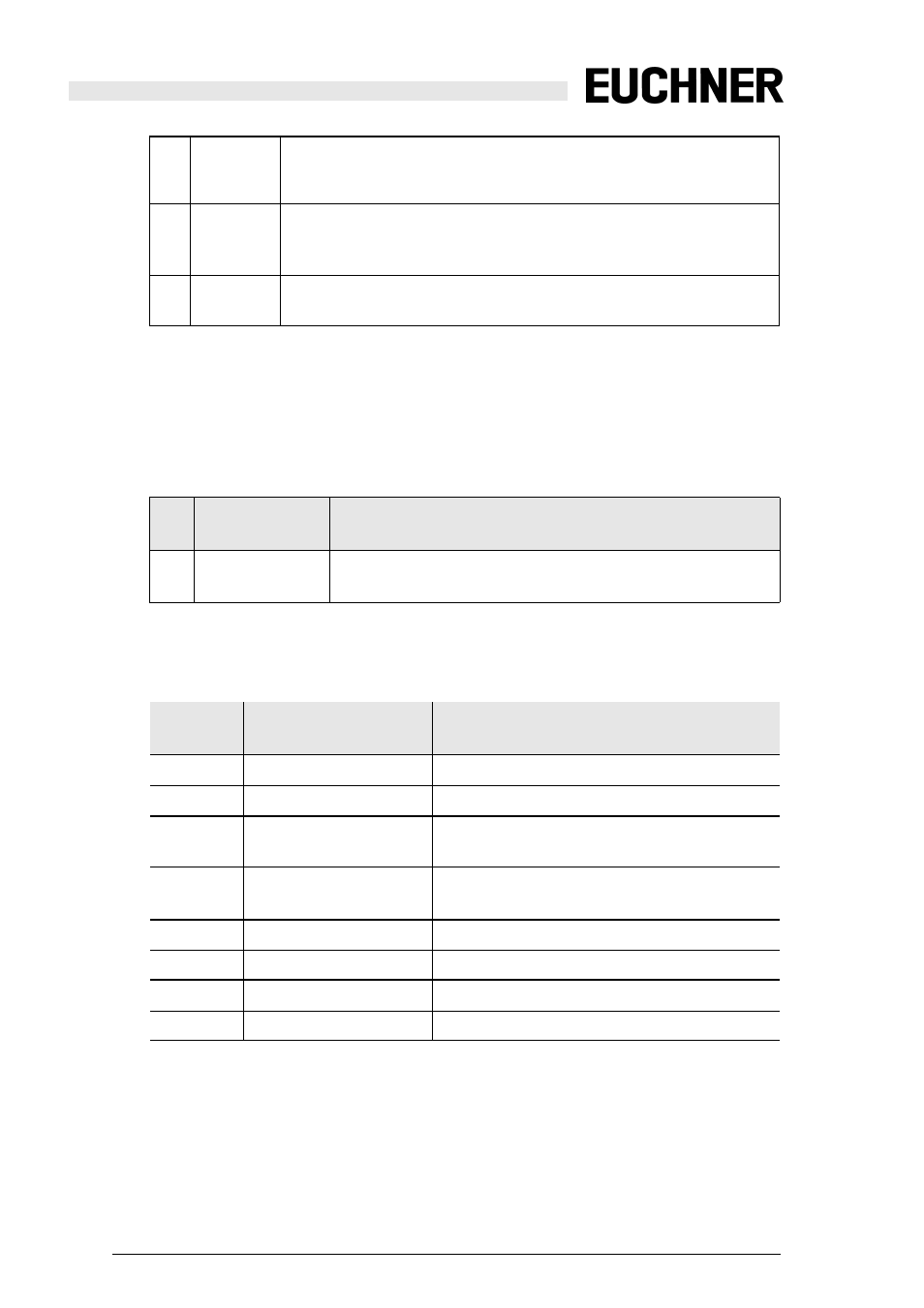
Channels 1 and 2 describe the states of the respective release circuits (OSSD’s)
of the Safety Monitor. For status codes and colors see section Status codes for
the release circuits (OSSD).
Channel 3 contains information as to whether there are warnings or faults in a re-
lease circuit for one or more devices assigned to this release circuit. The mean-
ings are as follows:
6.4.2.1
Status codes for the release circuits (OSSD)
AU
AUX 24V
The 24 V for supplying the safe outputs is present
1: 24 V for supplying the safe outputs is present
0: 24 V for supplying the safe outputs is not present
UA1 Warning
AS-i voltage OK, but less than 22.5 V
1: AS-i voltage greater than 22.5 V
0: AS-i voltage less than 22,5 V
S1-
S8
Switch
S1-S8: for a closed switch S1 … S8 '1' is entered at the correspond-
ing position.
YF
Yellow flashing
At least one of the devices associated with this release cir-
cuit is in the yellow flashing state
RF
Red flashing
At least one of the devices associated with this release cir-
cuit is in the red flashing state
Tab. 6-19.
Code
bit [3..0]
status / color
Description
0
green permanent lighting
output on
1
green flashing
delay time is running at stop category 1
2
yellow permanent light-
ing
start-up/restart-disable active
3
yellow flashing
external test necessary / acknowledgement
/ start delay active
4
red permanent lighting
output off
5
red flashing
error
6
grey or off
output not projected
7 ... F
reserved
Tab. 6-20.