Dakota Ultrasonics DFX-8 plus MANUAL1 User Manual
Page 54
Dakota Ultrasonics
50
3) Press the MEAS key once to highlight the WIDTH1 cell. Alternatively, use
the
UP and DOWN arrow keys on the left button wheel
4) Press the
LEFT and RIGHT
arrow keys on the right button wheel to
move the gate start to a position greater than 4 inches.
Note: CHECK YOUR CALIBRATION! Place the transducer back on the one
inch point, and any others in the given range, to confirm linearity. If the velocity
and zero values we calculated correctly, the thickness reading will match the
known thickness of the calibration standards. If the thickness is not correct,
repeat the steps above.
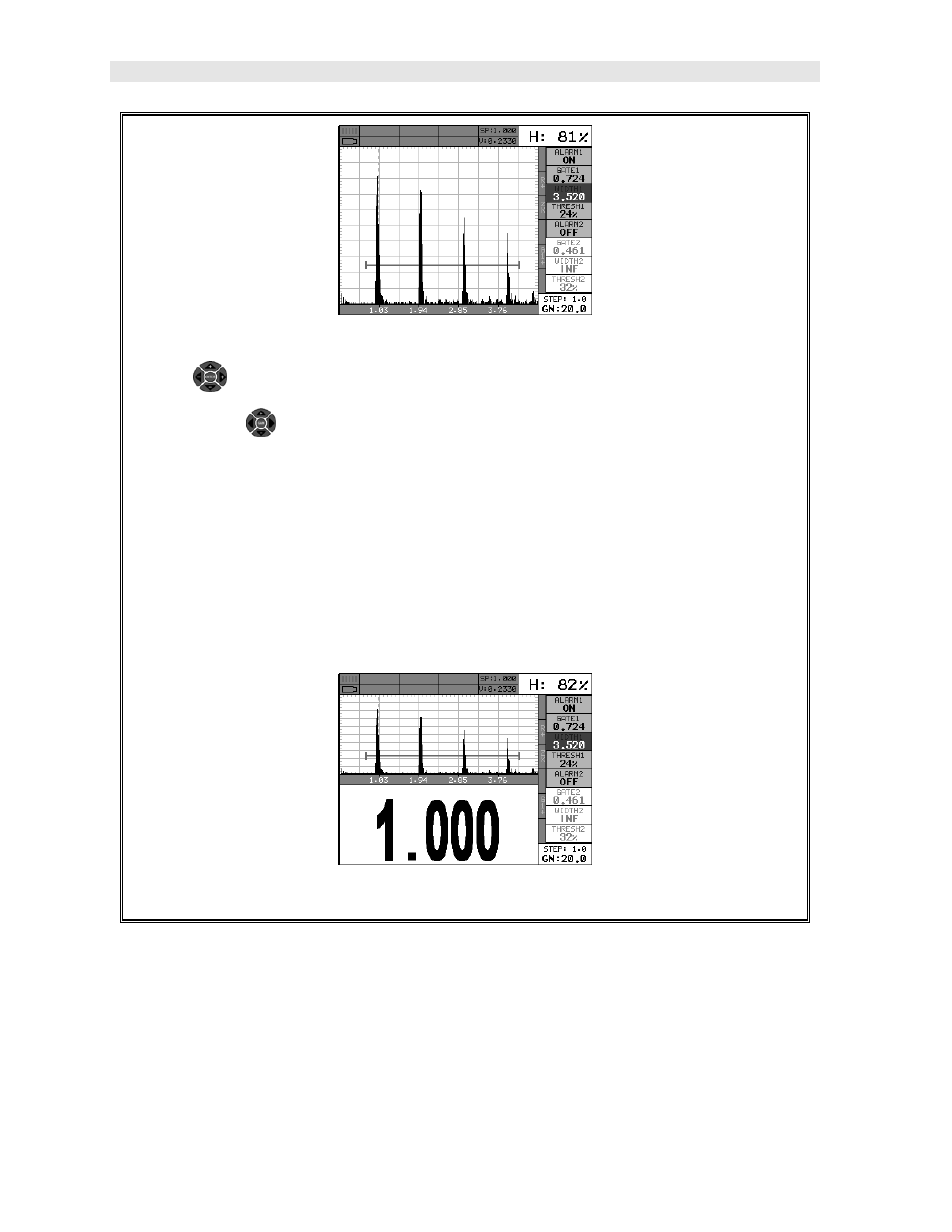
5) Press the OK key once to display the split screen with the thickness value.
5.3 Angle Beam Calibration
In the first example we demonstrated how to perform a two point calibration using a
single element straight beam contact transducer. With the exception of a handful of
additional comments, calibration using an angle beam transducer is virtually identical
in the scope of the overall step by step process. To avoid copying the procedures
from the previous section, we’ll focus only on the additional comments. Refer to