3 valves - theory of operation, Solenoid control valve, Valves - theory of operation -14 – JLG 460SJ ANSI Service Manual User Manual
Page 304: Solenoid control valve -14, Holding valve torque specification -14
SECTION 5 - HYDRAULICS
5-14
– JLG Lift –
3120788
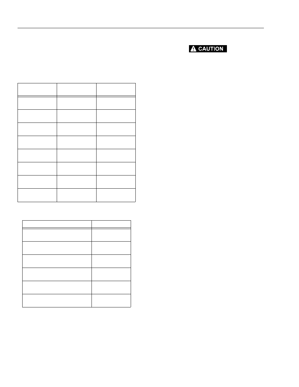
NOTE: If applicable, install the cartridge-type holding valve
and fittings in the rod port block, using new o-rings
as applicable. (See Table 5-2, Holding Valve Torque
Specification.)
Table 5-2. Holding Valve Torque Specification.
IF THE CYLINDER IS TO BE TESTED PRIOR TO INSTALLATION ON
THE MACHINE, EXTREME CARE SHOULD BE USED TO INSURE
THAT THE OUTER END OF THE ROD IS SUPPORTED. USE EITHER
A TRAVELING OVERHEAD HOIST, FORK-LIFT, OR OTHER MEANS
TO SUPPORT THE OVERHANGING WEIGHT OF THE EXTENDING
ROD.
5.3 VALVES - THEORY OF OPERATION
Solenoid Control Valve
Control valves used are four-way three-position solenoid
valves of the sliding spool design. When a circuit is acti-
vated and the control valve solenoid energizes, the spool
is shifted and the corresponding work port opens to per-
mit oil flow to the component in the selected circuit with
the opposite work port opening to reservoir. Once the cir-
cuit is deactivated (control returned to neutral) the valve
spool returns to neutral (center) and oil flow is then
directed through the valve body and returns to reservoir. A
typical control valve consist of the valve body, sliding
spool, and two solenoid assemblies. The spool is
machine fitted in the bore of the valve body. Lands on the
spool divide the bore into various chambers, which, when
the spool is shifted, align with corresponding ports in the
valve body open to common flow. At the same time other
ports would be blocked to flow. The spool is spring loaded
to center position, therefore when the control is released,
the spool automatically returns to neutral, prohibiting any
flow through the circuit.
Table 5-1. Cylinder Head and Tapered Bushing Torque
Specifications
Description
Head Torque Value
(Wet)
Tapered Bushing
Torque Value (Wet)
Lift Cylinder
120 ft. lbs.
(162 Nm)
9 ft. lbs
(12 Nm)
Lift Cylinder (SJ)
30 ft. lbs.
(41 Nm)
5 ft. lbs
(7 Nm)
Tele Cylinder
30 ft. lbs
(41 Nm)
9 ft. lbs
(12 Nm)
Level Cylinder
50 ft. lbs.
(68 Nm)
9 ft. lbs
(12 Nm)
Master Cylinder
50 ft. lbs.
(68 Nm)
9 ft. lbs
(12 Nm)
Level Cylinder (SJ)
50 ft. lbs.
(68 Nm)
9 ft. lbs
(12 Nm)
Axle Oscillation
Cylinder
30 ft. lbs.
(41 Nm)
N/A
Steer Cylinder
30 ft. lbs.
(41 Nm)
N/A
Description
Torque Value
SUN - 7/8 HEX M20 x 1.5 THDS.
30-35 ft.lbs.
(41-48 Nm)
SUN - 1 1/8 HEX 1-14 UNS THDS.
45-50 ft.lbs.
(61-68 Nm)
SUN - 1 1/4 HEX M36 x 2 THDS.
150-160 ft.lbs.
(204-217 Nm)
RACINE - 1 1/8 HEX 1 1/16-12 THDS.
50-55 ft.lbs.
(68-75 Nm)
RACINE - 1 3/8 HEX 1 3/16-12 THDS.
75-80 ft.lbs.
(102-109 Nm)
RACINE - 1 7/8 HEX 1 5/8-12 THDS.
100-110 ft.lbs.
(136-149 Nm)