JLG 460SJ ANSI Service Manual User Manual
Page 110
SECTION 3 - CHASSIS & TURNTABLE
3-56
– JLG Lift –
3120788
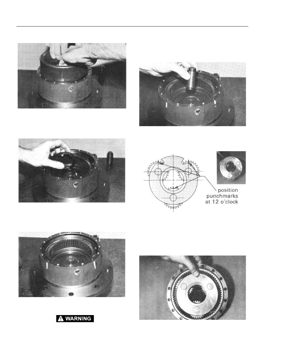
14. With the Hub Shaft Sub assembly resting on the
Shaft (1A), install Internal Gear (2). The Spline of the
Internal Gear (2) will mesh with the spline of the Out-
put Shaft (1A).
15. Thrust Washer (11) is installed on the face of the
Output Shaft (1A). Sufficient grease or petroleum
jelly should be used to hold thrust Washer (11) in
place.
16. Place “O” Ring (5) into Hub counterbore. Use petro-
leum jelly to hold “O” Ring in place.
BEWARE OF SHARP EDGES OF THE COUNTERBORE WHILE SEAT-
ING THE “O” RING.
Also at this time locate and mark the 4 counter
beamed holes in the face of the Hub (1G). This is for
Identification later in the assembly.
17. Thrust Spacer (9) is installed into the bore of the
Output Shaft (1A). This should be a slip fit and the
Thrust Spaces should rotate in this location.
18. Place Carrier Assembly (3) on a flat surface with the
large gears (3F) up and positioned as shown. Find
the punch marked tooth on each large gear (3F) and
locate at 12 o’clock (straight-up) from each planet
pin. Marked tooth will be located just under the car-
rier (3A) on upper two gears (3F).
19. With shoulder side of Ring Gear (4) facing down,
place Ring Gear over (into mesh with) large gears.