2 articulating jib, Removal, 3 limit switch adjustments – JLG 460SJ ANSI Service Manual User Manual
Page 272: Boom horizontal limit switch, Dual capacity angle limit switch, Boom length limit switch, Articulating jib -6, Removal -6, Limit switch adjustments -6, 2 articulating jib removal
SECTION 4 - BOOM & PLATFORM
4-6
– JLG Lift –
3120788
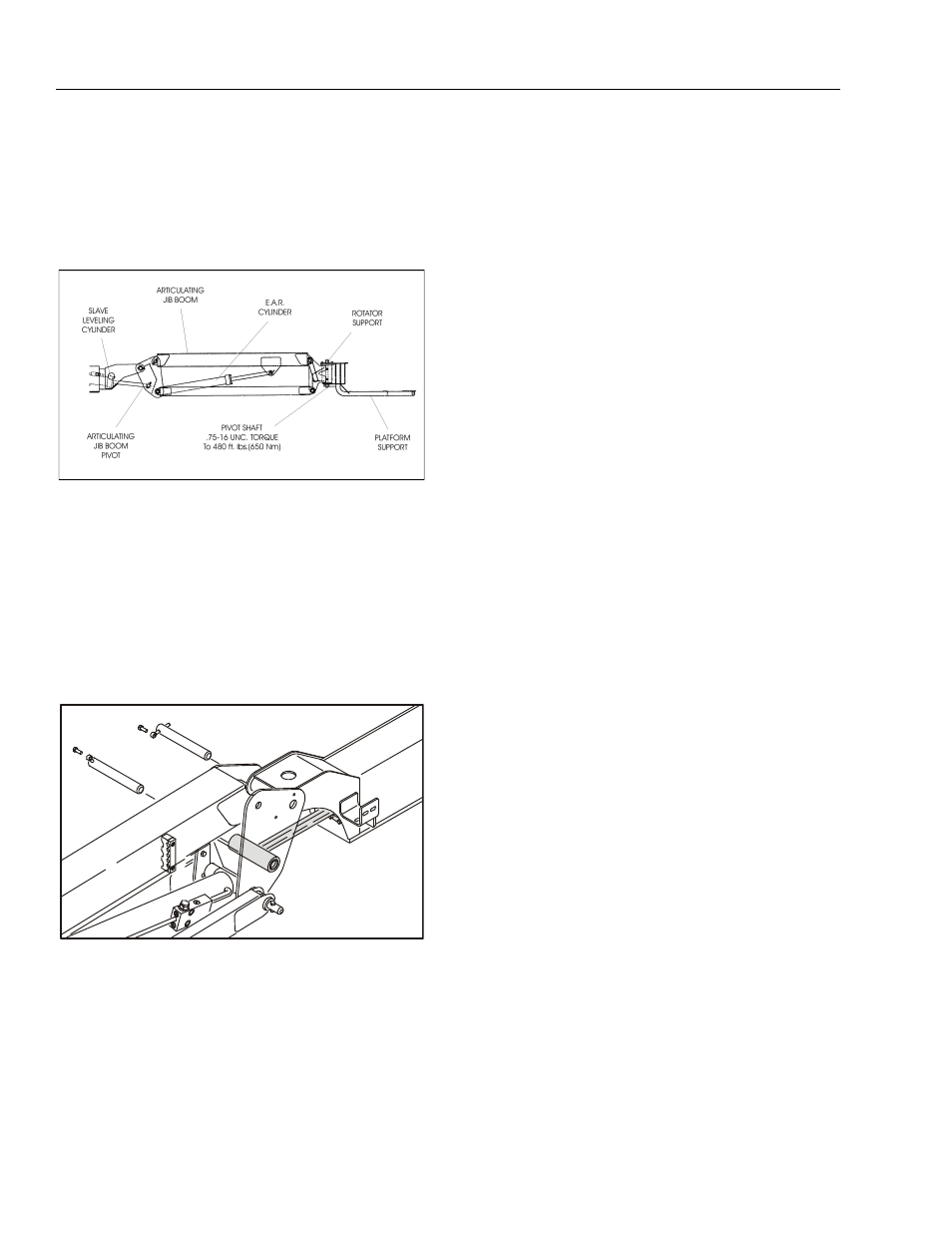
4.2 ARTICULATING JIB
Removal
1. Place the Articulating Jib in a horizontal position and
support the complete assembly with adequate
blocking.
2. Remove the Platform as outlined under Section 4.1,
3. Tag and disconnect the hydraulic lines running to
the Jib. Use a suitable container to collect any resid-
ual fluid. Cap the hydraulic lines and ports.
4. Remove the hardware securing the Jib pivot pin at
the boom. Using a suitable brass drift and hammer,
remove the pin from the fly boom. Use a suitable lift-
ing device and remove the Jib.
4.3 LIMIT SWITCH ADJUSTMENTS
See Figure 4-5., Figure 4-6., Figure 4-7., and Figure 4-8.
Boom Horizontal Limit Switch
1. Place machine on level surface.
2. Raise boom to 10 degrees horizontal. Limit switch
should activate before this point.
3. Lower the boom until limit switch resets. this should
be 1 degree above to 4 degrees below horizontal.
NOTE: Angle indicator should be placed on the top flat sur-
face of the boom, near the pivot point.
Dual Capacity Angle Limit Switch
1. Place machine on level surface.
2. Raise main boom to 10 degrees above horizontal.
limit switch should activate before this point.
3. Lower main boom until limit switch resets. this
should be 1 degree above to 4 degrees below hori-
zontal.
NOTE: Angle indicator should be placed approx. 2 ft. from
the main boom pivot pin and the attach point on the
main boom. Tower angle switch must be reset before
main boom angle switch can be activated.
4. Raise, extend, retract, and lower boom. Check for
smooth operation.
Boom Length Limit Switch
1. Place machine on a level surface.
2. Raise boom to approximate horizontal.
3. Extend the retracted fly boom. See Figure 4-5., Fig-
ure 4-6., or Figure 4-7. as applicable for the proper
dimension for switch activation.
Figure 4-4. Articulating Jib