JLG 460SJ ANSI Service Manual User Manual
Page 111
SECTION 3 - CHASSIS & TURNTABLE
3120788
– JLG Lift –
3-57
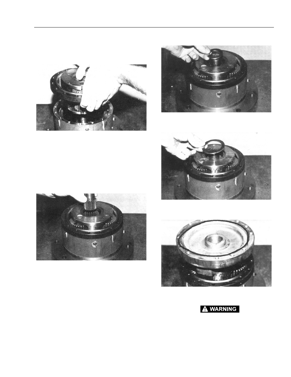
Be sure that punch marks remain in correct location
during Ring gear installation. The side of the Ring
Gear with “X” stamped on it should be up.
20. While holding Ring Gear (4) and Cluster Gear (3F) in
mesh, place small side of Cluster Gears (3F) into
mesh with the Internal Gear (13). On the Ring Gear
locate the hole marked “X” over one of the marked
counterbored holes (step 3) in Hub (1G).
NOTE: If gears do not mesh easily or Carrier Assembly
does not rotate freely, then remove the Carrier and
Ring Gear and check the Cluster Gear timing.
21. Input Gear (8) is installed, meshing teeth of the large
diameter Cluster Gear (3F). The counterbore on the
Input Gear (3F). The counterbore on the Input Gear
(8) locates on the shoulder of the Thrust Spacer (9).
This is to be a slip fit and operate freely.
22. Thrust Washer (10) is installed onto the Input Gear
(8) and should locate on the gear teeth shoulder.
23. Thrust Washer (11) is installed into the counterbore
of the Carrier (3).
24. Place “O” Ring (5) into cover (6) counterbore. Use
petroleum jelly to hold “O” Ring in place.
BEWARE OF SHARP EDGES OF THE COUNTERBORE WHILE SEAT-
ING THIS “O” RING.