Tapered bushing installation -13, Seating the tapered bearing -13, Poly-pak piston seal installation -13 – JLG 460SJ ANSI Service Manual User Manual
Page 303: Rod assembly installation -13
SECTION 5 - HYDRAULICS
3120788
– JLG Lift –
5-13
12. Tighten the capscrews evenly and progressively in
rotation to the specified torque value. (See Table 5-1,
Cylinder Head and Tapered Bushing Torque Specifi-
cations.)
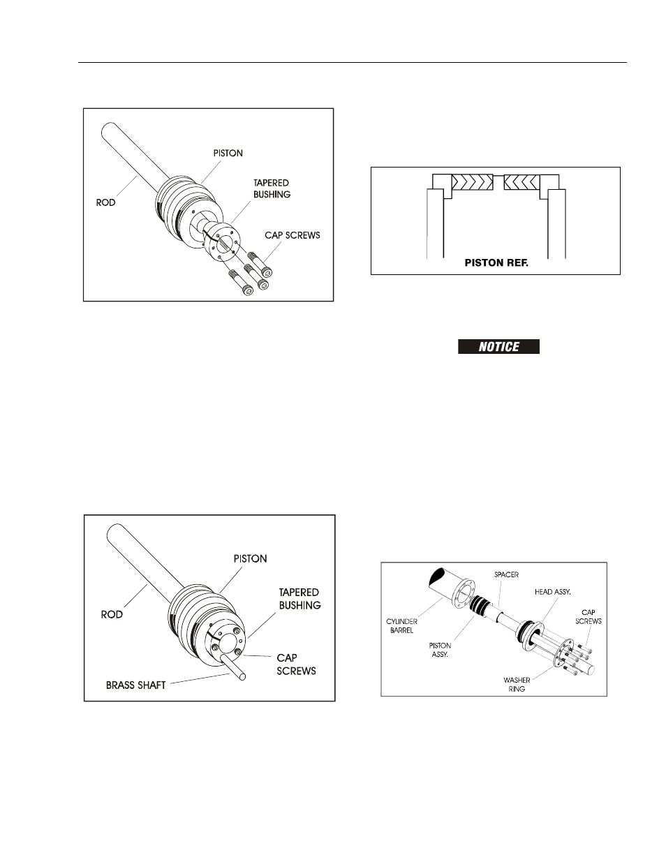
13. After the screws have been torqued, tap the tapered
bushing with a hammer (16 to 24 oz.) and brass
shaft (approximately 3/4” in diameter) as follows;
a. Place the shaft against the cylinder rod and in
contact with the bushing in the spaces between
the capscrews.
b. Tap each space once; this means the tapered
bushing is tapped 3 times as there are 3 spaces
between the capscrews.
.
14. Retorque the capscrews evenly and progressively in
rotation to the specified torque value. (See Table 5-1,
Cylinder Head and Tapered Bushing Torque Specifi-
cations.)
15. Remove the cylinder rod from the holding fixture.
16. Place new guide locks and seals in the applicable
outside diameter grooves of the cylinder piston.
(See Figure 5-17., Piston Seal Kit Installation.)
17. Position the cylinder barrel in a suitable holding fix-
ture.
EXTREME CARE SHOULD BE TAKEN WHEN INSTALLING THE CYL-
INDER ROD, HEAD, AND PISTON. AVOID PULLING THE ROD OFF-
CENTER, WHICH COULD CAUSE DAMAGE TO THE PISTON AND
CYLINDER BARREL SURFACES.
18. With barrel clamped securely, and while adequately
supporting the rod, insert the piston end into the
barrel cylinder. Ensure that the piston loading o-ring
and seal ring are not damaged or dislodged.
19. Continue pushing the rod into the barrel until the cyl-
inder head gland can be inserted into the barrel cyl-
inder.
20. Secure the cylinder head gland using the washer
ring and socket head bolts. See Figure 5-1, Cylinder
Head and Tapered Bushing Torque Specifications
21. After the cylinder has been reassembled, the rod
should be pushed all the way in (fully retracted) prior
to the reinstallation of any holding valve or valves.
Figure 5-18. Tapered Bushing Installation
Figure 5-19. Seating the Tapered Bearing
Figure 5-20. Poly-Pak Piston Seal Installation
Figure 5-21. Rod Assembly Installation