Mil output, J1939 diagnostic lamp configuration -147, Diagnostic corrective actions -147 – JLG 460SJ ANSI Service Manual User Manual
Page 201
SECTION 3 - CHASSIS & TURNTABLE
3120788
– JLG Lift –
3-147
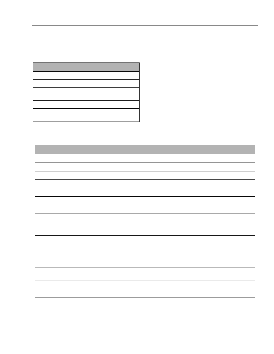
are assigned based on the configuration outlined in Table
3-14.
MIL Output
The MIL output is used to convey fault information to the
equipment operator. The MIL is always on (grounded)
when the system is in a key-on (Vsw), engine-off state.
This provides assurance that the output is functional. If a
DTC is logged as previously-active (historic), the MIL will
send a single flash for the “Blink on-time” every “Blink off-
time.”
Diagnostic Calibration Configuration and
Corrective Actions
Each fault within the DGC is capable of being uniquely
configured in the engine.s diagnostic calibration to cause
one or more corrective actions while a given fault is active.
Table 2 identifies the configuration options and corrective
actions available for configuration of each fault. The
desired action is set by the OEM calibration engineers.
Table 3-14. J1939 Diagnostic Lamp Configuration
ECI DIAGNOSTIC ACTION
J1939 LAMP
MIL
MIL
Soft Warning
Amber
Hard Warning, Low Rev Limit,
Shutdown
Red Stop
Power Derate 1 & 2
Protect
Forced Idle
None (use in combination with
other action)
Table 3-15. Diagnostic Corrective Actions
CORRECTIVE ACTION
DESCRIPTION
Enable
Enables the fault for fault detection
Shutdown
Cause an engine shutdown when fault becomes active
Never Forget
Retain fault as historic/previously active until cleared by a technician and does not allow historic fault to be “auto-cleared”
Turn on MIL
Turn on MIL output when fault becomes active
CL Disable
Disable closed-loop while the fault is active
CL Disable Key- Cyc
Disable closed-loop while the fault is active and for the remainder of the key cycle
AL Disable
Disable adaptive learn while the fault is active
AL Disable Key-Cyc
Disable adaptive learn while the fault is active and for the remainder of the key cycle
Power Derate 1
Limit TPS to the Power Derate 1 percent set in the diagnostic calibration while the fault is active. The Power Derate 1 TPS
percent should be set higher than Power Derate 2 as Power Derate 2 adds a higher level of protection.
Power Derate 2
Limit TPS to the Power Derate 2 percent set in the diagnostic calibration while the fault is active. If the calibration is set to
“Latched for Key-Cycle” Power Derate 2 remains active until engine speed and FPP conditions are satisfied. The Power
Derate 2 TPS percent should be set lower than Power Derate 1 as Power Derate 2 adds a higher level of protection.
Low Rev Limit
Limit RPM to the Low Rev Limit speed set in the diagnostic calibration while the fault is active. If the calibration is set to
“Latched for Key-Cycle” Low Rev Limit remains active until engine speed and FPP conditions are satisfied.
Forced Idle
Limit RPM to the Forced Idle speed set in the diagnostic calibration while the fault is active and for the remainder of the key
cycle
Soft Warning
Turn on the soft warning output when the fault becomes active
Hard Warning
Turn on the hard warning output when the fault becomes active
Stopped Check
Run fault detection/checking while the engine is in a key-on, engine-off condition. NOTE: It is recommended that this fea-
ture only be used for general sensor faults (high/low voltage) and some output drivers