General, General -79, Position controller truth table -79 – JLG 460SJ ANSI Service Manual User Manual
Page 133
SECTION 3 - CHASSIS & TURNTABLE
3120788
– JLG Lift –
3-79
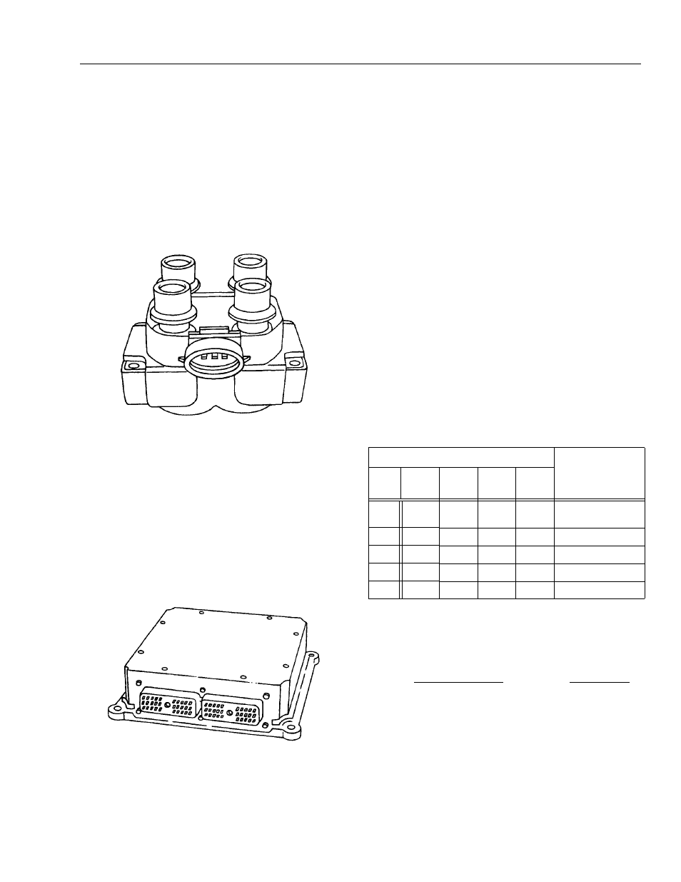
IGNITION COIL
The electronic ignition system uses a coil pack with one
ignition coil for each two cylinders in the engine. Each cyl-
inder is paired with its opposing cylinder in the firing order,
so that one cylinder on compression fires simultaneously
with the opposing cylinder on exhaust. The spark that
occurs in the cylinder on the exhaust stroke is referred to
as a “waste spark.”
The primary coils in the coil pack are triggered by the
“Ignition Coil Feed #1” and “Ignition Coil Feed #2” Signals
from the ECM.
ENGINE CONTROL MODULE (ECM)
The ECM is responsible for maintaining proper spark and
fuel injection timing for all operating conditions. To provide
optimum operation and emissions, the ECM monitors the
input signals from the following components in order to
calculate spark timing:
• Engine coolant temperature (ECT) sensor
• Intake air temperature (IAT) sensor
• Throttle position sensor
• Crankshaft position sensor
3.20 THROTTLE CHECKS AND ADJUSTMENTS
- DEUTZ ENGINE (PRIOR TO S/N 61718)
General
The throttle control system on the Deutz engine includes
the positional controller and the actuator.
Four LEDs are incorporated in the controller. They are as
follows:
• Red - failure: signals a problem with the system -
needs service or adjustment
• Green - clutch engaged; operation normal while sys-
tem is powered.
• Amber - motor extend
• Amber - motor retract
The controller is designed so that when the system volt-
age reaches 10.5 volts, the actuator clutch will be
released and the motor drive turned off in order to prevent
unpredictable operation from occurring.
When a failure condition occurs (i.e. position time-out) the
controller will release the clutch and turn off the actuator
motor. This will prevent unnecessary motor wear.
Table 3-10. Position Controller Truth Table
Control Wiring
Actuator Position
TRIM
POT #
Black
Red
White
Green
GND
OFF
X
X
OFF POSITION
(FREEWHEEL)
1
GND
+12 VDC
OFF
OFF
IDLE - 1200 rpm
2
GND
+12 VDC
+12 VDC
OFF
MID - 1800 rpm
3
GND
+12 VDC
OFF
+12 VDC
NOT USED
4
GND
+12 VDC
+12 VDC
+12 VDC
HIGH - 2900 RPM
GND = POWER SUPPLY OR BATTERY GROUND
OFF = GROUND OR OPEN CIRCUIT
X = DON’T CARE
+12 VDC = +12 VOLT POWER SUPPLY OR BATTERY SYSTEM, VIA A 5
AMP FUSE OR CIRCUIT BREAKER
TRIMMER ADJUSTMENTS
LED INDICATORS
1 - POSITION 1 CW=RETRACT
2 - POSITION 2 CW=RETRACT
3 - POSITION 3 CW=RETRACT
4 - POSITION 4 CW=RETRACT
R - RETRACT INDICA-
TOR (AMBER)
E - EXTEND INDICATOR
(AMBER)
C - CLUTCH INDICATOR
(GREEN)
F - FAILURE INDICATOR
(RED)