Chapter 3. operation 40, Tsu 600, Figure 3-1 – ADTRAN TSU 600 User Manual
Page 52: Display panels remote, Module status
Chapter 3. Operation
40
TSU 600 User Manual
61200.076L2-1
OK
• 1
MODULE
TEST
TSU 600
ALARM
OK
• 2
TEST
ALARM
OK
• 3
TEST
ALARM
ALARM
ERROR
TEST
COPY
HOME
SHIFT
OK
REMOTE
A
B
C
REMOTE
ALARM
CLEAR
D
E
F
0
#
1
2
3
7
8
9
4
5
6
CANCEL
ENTER
OK
• 5
TEST
ALARM
OK
• 4
TEST
ALARM
OK
• 6
TEST
ALARM
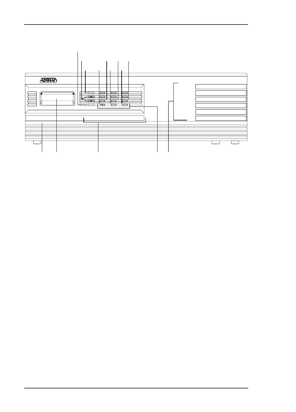
1. REMOTE
2. LCD Window
3. CSU Status
4. Key Pad
5. Module Status
6. CANCEL
7. Up and Down Arrow Keys
9
11
13
1
3
2
7
10
12 14
6
8
4
5
8. ENTER
9. COPY
10. REMOTE
11. HOME
12. ALARM
13. SHIFT
14. CLEAR
Figure 3-1
TSU 600 Front Panel Layout
The display panels and operation keys called out in
Figure 3-1 are described in the following sections:
Display Panels
Remote
When illuminated, this panel indicates that the TSU
600 is accessed remotely by the PC program.
Module Status
The module status LEDs display the operational
condition of ports installed in the option slots.
• OK (green)
Indicates the operation is in the normal mode and
no errors have been detected.
- Express 4110 (205 pages)
- Gigabit Ethernet Multi-Mode Fiber Tributary Module 1184519L1 (2 pages)
- U-BR1TE ISDN 2B1Q (4 pages)
- DSU/CSU (6 pages)
- 3010 (30 pages)
- NetVanta 1024 (2 pages)
- FT1 (10 pages)
- IP Mini-DSLAM (2 pages)
- 6530 (20 pages)
- 6530 (2 pages)
- AHT1U (2 pages)
- DS3 MX (2 pages)
- 600R (264 pages)
- DUAL Nx56/64 1200142L1# (42 pages)
- NetVanta T1/FT1 + DSX-1 (2 pages)
- IQ SERIES 56 (1 page)
- 1200070L2 (187 pages)
- 1200051L2 (165 pages)
- NETVANTA 3120 (2 pages)
- 1200 (2 pages)
- NetVanta Series (2 pages)
- 850 (4 pages)
- ATLAS 800 Series Module QUAD E1 (2 pages)
- Atlas 830 (2 pages)
- TSU LT (2 pages)
- Express L1.5 (2 pages)
- MX2820-48 VDC M13 MUX (2 pages)
- Dial Backup Interface Module 1204006L2 (2 pages)
- 900 Series (2 pages)
- Atlas 550 (1 page)
- Atlas 550 (262 pages)
- NetVanta 5305 (2 pages)
- 1200350L1 (134 pages)
- ATM Mini-DSLAM (2 pages)
- D4-n x 64 DSU DP (4 pages)
- Type 400 (4 pages)
- 1204002L1 (163 pages)
- NetVanta ADSL (2 pages)
- 3000 HTU-C (2 pages)
- 600e (2 pages)
- 1200F (2 pages)
- D4 TRI-C DP (1 page)
- 239 T1 HDSL4 (20 pages)
- 3000 NTU-8 (18 pages)
- 1200130L1 (153 pages)