Wiring termination, Fd67 bus output addressing – Norgren VS18 Series Valve Advantage User Manual
Page 84
VS18/VS26
MAINTENANCE & INSTRUCTION BOOKLET
8.7.2 Wiring
termination
If the VS18/VS26 FD67 valve island is the last module in a branch, the extension interface of
the internal system connection must always be fitted with a terminal resistance.
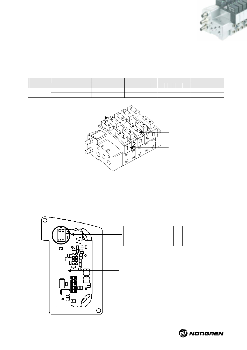
8.7.3 FD67 bus output addressing
Data byte_0
Data byte_1
Data byte_2
Data byte_3
Valve no.
¨
1
2
3
4
5
6
7
8
9 10 11 12 13 14 15 16
Solenoid
14
0 2 4 6 8 10 12 14 16 18 20 22 24 26 28 30
Data bits
Solenoid
12
1 3 5 7 9 11 13 15 17 19 21 23 25 27 29 31
Solenoids 14
Solenoids 12
Valve no.
Number of configured output bytes
The number of configured output bytes can be changed if required. The default setting is always
on the maximum. To change the number of outputs you have to remove the Fieldbus PCB and
modify the DIP switch as follows:
switch1
0 0 1 1
switch2
0 1 0 1
output
bytes
1 2 3 4
Fieldbus PCB
(mounted on the E-connector-kit)
VS2672926-KG00E_05/07 Page
84/97