Devicenet, Devicenet pin assignment, Devicenet wiring – Norgren VS18 Series Valve Advantage User Manual
Page 59: Evice, Devicenet section, Devicenet) and
VS18/VS26
MAINTENANCE & INSTRUCTION BOOKLET
8.3 D
EVICE
N
ET
Norgren DeviceNet Fieldbus systems conform to DeviceNet
specification volume 1 release 2 and the Pneumatic Valve
Device Profile.
Communication system:
2-wire CAN hardware communication protocol
Number of nodes per network:
Master + 62 slaves
Bus topology:
Line
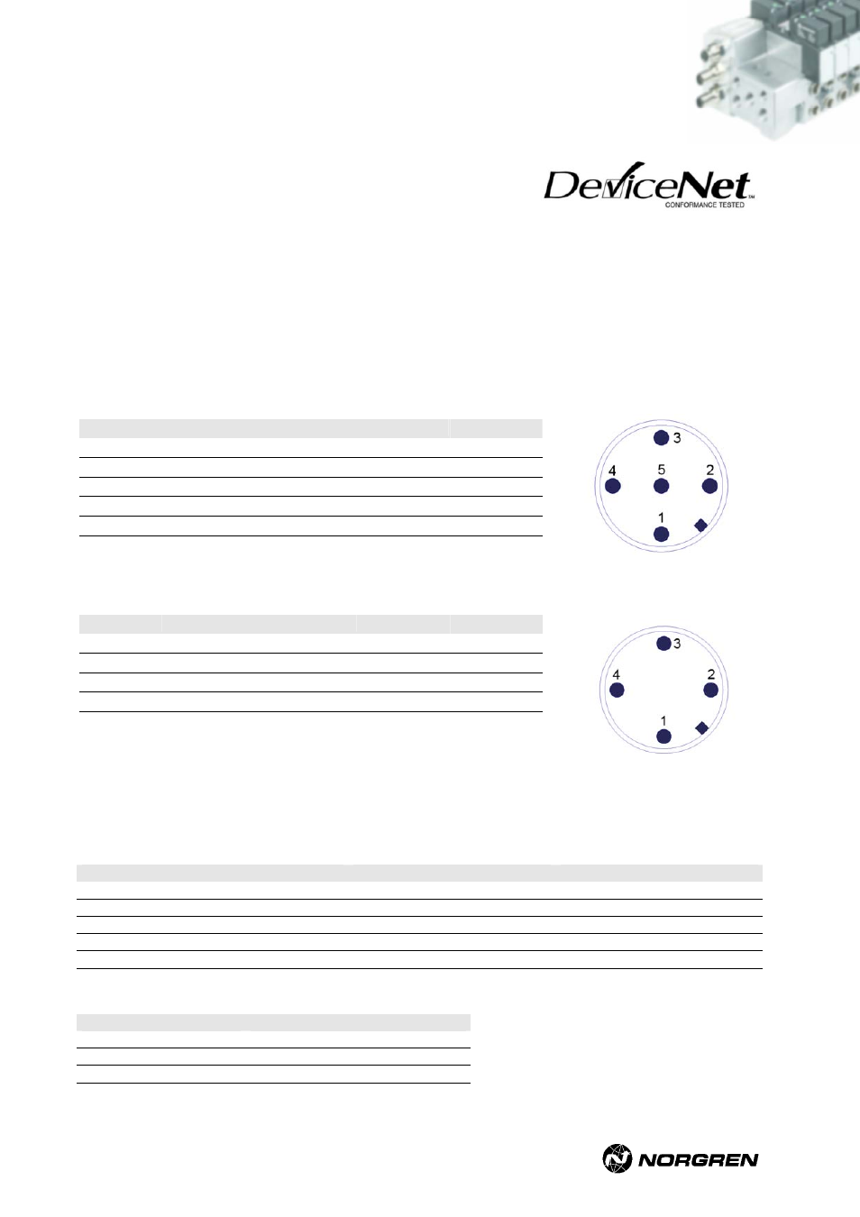
8.3.1 DeviceNet pin assignment
M12 5-pin bus connector (A-coded / IP65)
Male
Looking into node connector
Pin no.
Function
Tolerance
Max. current
1 CAN_SHLD
- -
2 CAN_V+
1)
+/-25% 200mA
3 CAN_GND
- -
4 CAN_H
- -
5 CAN_L
- -
1)
Must be galvanic isolated to 24 VA valves.
M12 4-pin power connector
Male
Pin no.
Function
Tolerance
Max. current
1 -
- -
2
24 VA valves
+/-10%
1)
3 0
volt
- -
4 Earth
- -
Looking into node connectors
1)
I
max
= 10mA + n * 60mA
n = number of energized solenoids
8.3.2 DeviceNet
wiring
Line parameter
Parameter
Line A (thick cable)
Line B (thin cable)
Impedance in Ohms
120 +/-10%
120 +/-10%
Capacitance per unit length (pF/m)
12
12
Jacket Marking
Vendor name & part number
Vendor name & part number
Core diameter (mm)
#18 Copper 19 Strands
#24 Copper 19 Strands
Outside diameter
0.41 – 0.49 inches
0.24 – 0.28 inches
Line lengths
Baud rate (kBit/s)
Trunk cable length (max.) in m
125 500
250 250
500 100
VS2672926-KG00E_05/07 Page
59/97