Power supply and pin assignment, Max. current load on valve connectors, 1 power supply and pin assignment – Norgren VS18 Series Valve Advantage User Manual
Page 48: 2 max. current load on valve connectors
VS18/VS26
MAINTENANCE & INSTRUCTION BOOKLET
8.1.1 Power supply and pin assignment
VS18/VS26 Fieldbus valve islands are designed to be used with a protective extra low voltage
(PELV) power supply (UL Class 2 Supply only) according to IEC 364-4-41. As a result, an earth
connection for safety reasons is not required because the supply voltage is restricted to a
maximum of 42.2 volts even under fault conditions. However, the earth must be connected. It is
not a protective earth, but is required to provide EMC shielding.
The power supply of the Fieldbus valve islands (excluding the version with AS-Interface or
FD67 bus) are made by an 4-pin M12 connector. Using Profibus DP, a 5-pin 7/8“ connector is
also available.
Male
M12 4-pin power connector for Fieldbus
Looking into node connectors
Pin no.
Function
Tolerance
Max. current
1
24 VB logic circuit supply
+/-25%
300mA
2
24 VA valves
+/-10%
1)
3 0
volt
-
2)
4 Earth
- -
Note:
Both DeviceNet and CANopen nodes do not use pin 1 of the M12 power connector. This is due
to the power for the logic circuit being drawn from the network connection. For details on pin
assignment please refer to sections
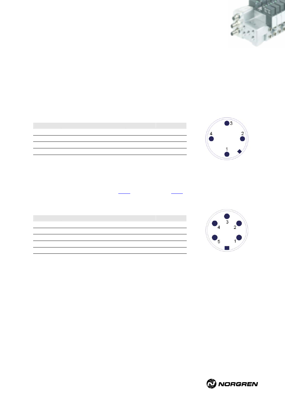
Male
7/8” 5-pin power connector for Profibus DP
Looking into node connectors
Pin no.
Function
Tolerance
Max. current
1 -
- -
2 0
volt
-
2)
3 Earth
- -
4
24 VA valves
+/-10%
1)
5
24 VB logic circuit supply
+/-25%
300mA
1)
I
max
= 10mA + n * 60mA
n = number of energized solenoids
2)
I
max
=
I
VA
+
I
VB
8.1.2 Max. current load on valve connectors
The digital outputs for activation the pilot valves are optimised for Norgren VS18/VS26 valves.
Among compliance of the following data, it is possible to use items from other manufacturers:
• Maximum current: I
max
= 85mA (if VA = 24V DC)
• Limitation of the inductive interrupting to U < 40V
• Pin assignment according to ISO 15407-2
• Output voltage: U
output
= U
supply
– 0.9V
VS2672926-KG00E_05/07 Page
48/97