Norgren VS18 Series Valve Advantage User Manual
Page 18
VS18/VS26
MAINTENANCE & INSTRUCTION BOOKLET
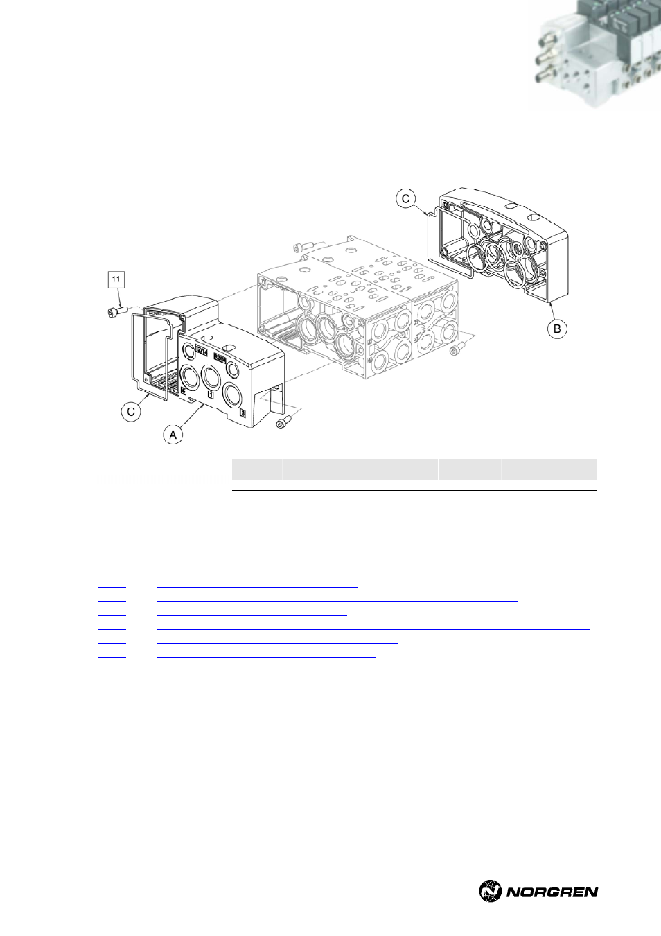
2. Mount the left and right end plate to the modular sub-base. Ensure end plates are properly
aligned and the end plate gasket is fitted. Then tighten the mounting screws (two per end
plate) with the specified torque. If you are using a power screwdriver, consider the maximum
speed allowed.
Screw
Type
(thread)
Valve
seize
Tightening
torque in Nm
Tightening
torque in Ibs
Max. screw driver
speed in r.p.m.
11
M3x10
VS18
0.8 – 0.9
7.08 – 7.96
1100
11
M4x12
VS26
1.0 – 1.1
8.85 – 9.73
1100
3. Having assembled the base of the valve island, proceed with the electronic components. For
these instructions please refer to following sections:
D-Sub assembly / Installation of PCB
NPTF1” conduit entry with terminals assembly / Installation of PCB
M23 assembly / Installation of PCB
Fieldbus assembly / Installation of PCBs (excluding AS-Interface and FD67 bus)
AS-Interface assembly / Installation of PCBs
FD67 bus assembly / Installation of PCB
VS2672926-KG00E_05/07 Page
18/97