Search
beautypg.com
Directory
Brands
Kramer Electronics manuals
Accessories for electrical
SV-551
Manual
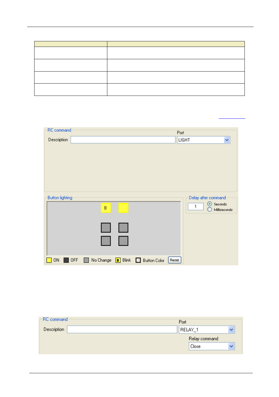
2 the light rc command area, 3 the relay port rc command area, Figure 22: light rc command area – Kramer Electronics SV-551 User Manual
Page 28: Figure 23: relay port rc command area, Table 6
Text mode
Original mode
2 the light rc command area, 3 the relay port rc command area, Figure 22: light rc command area | Figure 23: relay port rc command area, Table 6 | Kramer Electronics SV-551 User Manual | Page 28 / 51
Pages:
1
…
26
27
28
29
30
…
51
wrong Brand
wrong Model
non readable
This manual is related to the following products:
RC-63DLN
RC-63DL
RC-63D
RC-63AX
RC-63AL
RC-63A
RC-62X
RC-62
RC-52N
RC-2
See also other documents in the category Kramer Electronics Accessories for electrical:
VM-114H
(22 pages)
VM-114H2C
(25 pages)
VM-114H4C
(23 pages)
VS-81ETH
(27 pages)
VS-81ETH
(41 pages)
VM-9T
(13 pages)
VP-12NHD
(15 pages)
VP-5R
(20 pages)
VP-6A
(15 pages)
PT-5R/T
(13 pages)
TP-102HD
(13 pages)
TP-104HD
(33 pages)
TP-112HD
(13 pages)
TP-114
(13 pages)
TP-202
(15 pages)
TP-205A
(15 pages)
TP-210
(14 pages)
TP-210A
(15 pages)
tp-219hd
(16 pages)
TP-305A
(15 pages)
TP-310A
(18 pages)
TP-410
(34 pages)
VM-1H4C
(17 pages)
VP-200xlT
(31 pages)
VP-300THD
(12 pages)
VPM-2
(42 pages)
SI-1VGA
(2 pages)
SID-DP
(2 pages)
SID-DVI
(2 pages)
SID-H
(2 pages)
SID-VGA
(2 pages)
SID-X1
(2 pages)
SID-X1
(23 pages)
SID-X1N
(23 pages)
SID-X2N
(31 pages)
SID-X3N
(22 pages)
622R
(17 pages)
VS-169TP
(7 pages)
VS-169TP
(45 pages)
WSI-1VGA
(2 pages)
TP-107AV
(32 pages)
RC-5B2
(137 pages)
WP-500
(2 pages)
SV-552
(22 pages)
WP-501
(16 pages)