Hmi (human-machine interface) – NOVUS V1.5x A User Manual
Page 91
NOVUS AUTOMATION
www.fieldlogger.net
91/103
HMI (HUMAN-MACHINE INTERFACE)
The HMI (Human-Machine Interface) is available as an accessory to the FieldLogger. Several features are implemented
in this device, such as enabled channels monitoring, viewing these channels in chart mode, alarms monitoring, status
checking and configuration of some basic FieldLogger operation parameters.
Fig. 25 – FieldLogger with HMI
The HMI is attached to the FieldLogger through a DB9 connector located under its cover. The Fig. 10 and 11
demonstrate how the IHM is connected to FieldLogger.
Both power and serial communication go through the DB9 connector, so it is the only necessary connection. There is
also the possibility of using the IHM remotely, attached to the FieldLogger through an extension cable. As the
communication between IHM and FieldLogger is done through RS485 using a baud rate of 115200 bps what puts a limit
to the HMI operation distance is the power, what means that the voltage drop in the power cables (both positive and
negative cables summed) must be 0.4 V top. Considering a current consumption of 80 mA, it makes the maximum cable
resistance to be 5 ohms. As cable resistance per meter depends mainly on its section, we recommend checking a wire
resistance table. For some common cables, HMI’s maximum operation distance is shown in Table 02.
Gauge
Section
Maximum Length
24 AWG
0.21 mm
2
29 m
22 AWG
0.33 mm
2
47 m
20 AWG
0.52 mm
2
75 m
Table 02 – Wire resistance
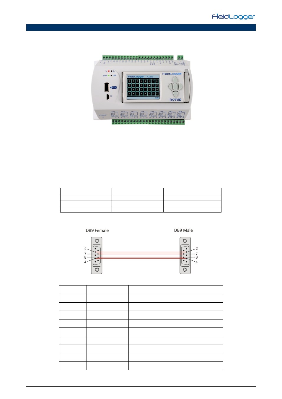
Figure 26 below shows the pin-out needed to build an extension cable to the HMI.
Fig. 26 – Building an extension cable
PIN
SIGNAL
DESCRIPTION
1
-
-
2
+5 V
HMI power input: +5 Vdc
3
-
-
4
B / D1 / D+ / D
RS485 Tx/Rx positive data
5
-
-
6
-
-
7
GND
HMI power input: ground
8
A / D0 / D- / D\
RS485 Tx/Rx negative data
9
-
-
Table 03 – Pin-out for building the DB9 connectors