2 hardware configuration, 1 opening the configuration door, 2 configuration of the dip-switches – Videotec NXPTZT User Manual
Page 20: 3 setting the configuration check mode, Dip 2, En - english - i nstruc tions manual, Fig. 14, J4 fig. 15, Fig. 16, Fig. 17
EN - English - I
nstruc
tions manual
20
MNVCNXPTZT_1343_EN
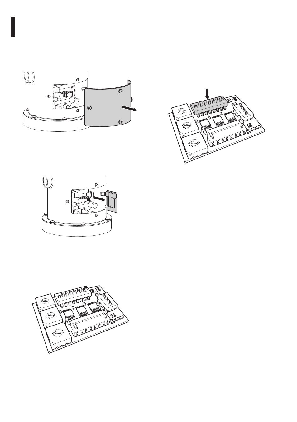
7.2 Hardware configuration
7.2.1 Opening the configuration door
Before powering the device it must be configured
correctly by setting the dip-switches inside the
configuration hatch. Open the hatch by undoing the
screws as shown in figure.
Fig. 14
7.2.2 Configuration of the dip-switches
Take the configuration board from its J4 connector on
the connector board.
J4
Fig. 15
This board is used to set the communication
parameters of the serial lines RS-485-1 and RS-485-
2: the address of the receiver, the communication
protocol and baud rate.
1 2
3 4 5
6 7
8
9
0
1 2
3 4 5
6 7
8
9
0
1 2
3 4 5
6 7
8
9
0
0A
ON
1 2
3 4
5
6 7
8
U2
U1
U3
D
IP
3
D
IP
5
D
IP
4
1
2
3
4
Fig. 16
7.2.3 Setting the configuration check
mode
To set the operating mode operate on DIP 2.
SW 1=ON: Display Configuration. To be used only to
verify the configuration at the end of the setting. To
be used only to verify the configuration at the end of
the setting. During normal operation make sure the
lever is on OFF (SW 1=OFF).
1 2
3 4 5
6 7
8
9
0
1 2
3 4 5
6 7
8
9
0
1 2
3 4 5
6 7
8
9
0
0A
ON
1 2
3 4
5
6 7
8
U2
U1
U3
D
IP
3
D
IP
5
D
IP
4
1
2
3
4
DIP 2
Fig. 17