4 preparatory work before installation, 1 fixing to parapet or ceiling mount – Videotec NXPTZT User Manual
Page 13
Instruc
tions manual - English - EN
13
MNVCNXPTZT_1343_EN
6.4 Preparatory work before
installation
Use appropriate tools for the installation.
The particular nature of the site where the
device is to be installed may mean special
tools are required for installation.
Choose an installation surface that is
strong enough to sustain the weight of
the device, also bearing in mind particular
environmental aspects, such as exposure to
strong winds.
It should be installed so that no one can be
hit by moving parts. It should be installed
so that moving parts cannot hit other
objects and create hazardous situations.
Make sure the appliance is securely
anchored before supplying power.
The device must be installed and
maintained only and exclusively by
qualified technical personnel.
For technical services, consult only and
exclusively authorized technicians.
Since the user is responsible for choosing
the surface to which the unit is to be
anchored, we do not supply the fixing
devices for attaching the unit firmly to
the particular surface. The installer is
responsible for choosing fixing devices
suitable for the specific purpose on hand. In
general use methods and materials capable
of supporting at least four times the weight
of the device.
It is possible to install the unit with several brackets.
We strongly recommend using only approved
brackets and accessories during installation.
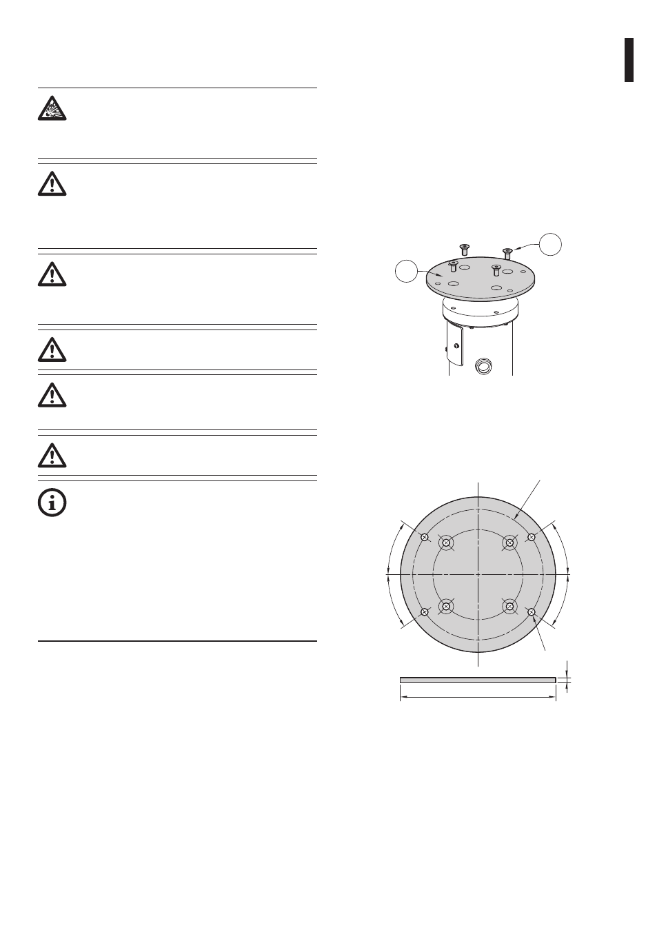
6.4.1 Fixing to parapet or ceiling mount
Attach the adapter (01) to the bottom of the unit
using 4 stainless steel (A4 class 80) socket flat head
cap screw M10 x 20mm (02).
Make sure the thread are free of dirt and debris.
Apply a generous amount of thread locking
compound (Loctite 270) into the threaded holes in
the base of the device.
Tighten them to 35Nm. The thread compound
must cure for one hour, allow for this period prior to
completing the installation.
01
02
Fig. 5
Use the external holes in the adapter to fix the
assembled unit to the wall or to the pole. Use screws
that can bear at least 4 times the weight of the unit.
Ш 11
8
Ш 238
Ш 200
35
35
35
35
Fig. 6