5 connection of the ethernet cable, 6 telemetry line connections – Videotec NXPTZT User Manual
Page 18
EN - English - I
nstruc
tions manual
18
MNVCNXPTZT_1343_EN
7.1.5 Connection of the Ethernet cable
Operating mode valid only on version with
IP board.
Telemetry transmission and video signal
pass through the Ethernet cable. Do not
connect cable RS-485 and the video cable.
The multicore cable has 2 Ethernet B-type numbered
cables inside. Cable number 1 corresponds to the
IP output of the standard camera. Cable number 2
corresponds to the IP output of the thermal camera.
(if present).
Perform the connections following the instructions
reported in the table .
CONNECTION OF THE ETHERNET CABLE
Pin number
Cable color
1
Orange-White
2
Orange
3
Green-White
4
Blue
5
Blue-White
6
Green
7
Brown-White
8
Brown
Tab. 2
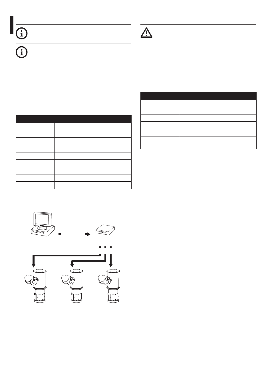
Both cables must be crimped in the same way.
The example below shows a typical installation.
Hub / Switch
Personal
Computer
UTP cat 5E
UTP cat 5E
Fig. 12
7.1.6 Telemetry line connections
The installation is type TNV-1, do not
connect it to SELV circuits.
The cables allow access to 2 RS-485 serial
communication lines.
The lines can be configured in various ways according
to the dip-switch settings of the configuration board (
Fig. 16, page 20).
Telemetry lines connect the device to control and
programming units (keyboard or PC).
TELEMETRY LINE CONNECTIONS
Cable color
Description
Yellow
RS-485-1 line, A (+)
Red
RS-485-1 line, B (-)
Blue
RS-485-2 line, A (+)
White
RS-485-2 line, B (-)
Black
External washer tank level monitoring
(if present)
Tab. 3