7 alarm and relay connections, 2 relay connection – Videotec NXPTZT User Manual
Page 19
Instruc
tions manual - English - EN
19
MNVCNXPTZT_1343_EN
7.1.7 Alarm and relay connections
The unit is provided with 5 clean contact alarms and
2 output relays with clean contact.
ALARM AND RELAY CONNECTIONS
Cable color
Description
Brown-Green
Relay 2, Terminal A
Green-White
Relay 2, Terminal B
Red-Blue
Relay 1, Terminal A
Grey-Pink
Relay 1, Terminal B
Green
Common alarms, A1-A2-A3-A4-A5, mass
alarms
Yellow-White
Alarm 5 (clean contact)
Pink
Alarm 4 (clean contact)
Grey
Alarm 3 (clean contact)
Violet
Alarm 2 (clean contact)
Brown
Alarm 1 (clean contact)
Tab. 4
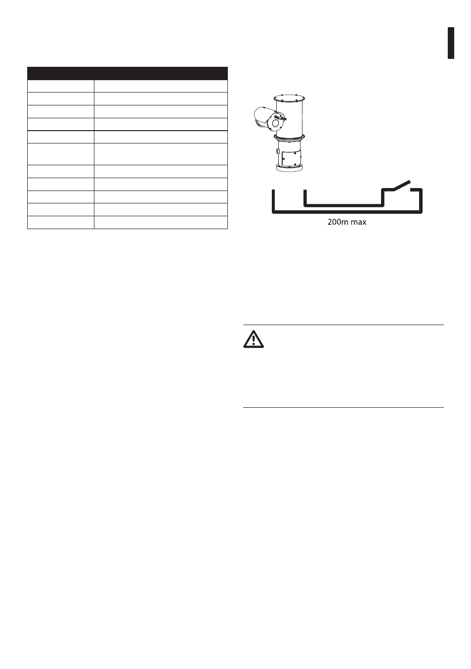
All alarms have an approximate reach of 200m,
which can be obtained using a shielded cable with a
minimum section of 0.25mm² (AWG 30).
7.1.7.1 Connecting an alarm with clean
contact (dry contact)
For a clean contact alarm (alarms AL1, AL2, AL3, AL4,
AL5), implement the connection as shown in the
figure.
AL1
COM
Dry contact
Fig. 13 AL1: Alarm 1. COM: Common alarms.
The clean contact alarm can be NO (normally open)
or NC (normally closed).
For further details on configuring and using the
alarms, refer to the related chapter (9.1.8.1 Alarms
Menu, page 44).
7.1.7.2 Relay connection
Relays can be used for low working
voltages only (up to 30Vac or 60Vdc) and
with a maximum current of 1A. Use cables
with a section suitable for the load to be
controlled and use cables with a minimum
section of 0.25mm² (AWG 24) and maximum
section of 1.5mm² (AWG 16).
Relays do not have polarity and therefore both
terminals of the same relay can be swapped for
alternating or continuous current voltages.
For further details on configuring and using the
relays, check the relative chapter (9.1.8.1 Alarms
Menu, page 44).