3 dvc22, Dvc22 – High Country Tek DVC80 User Manual
Page 82
P/N: 021-00154, Rev. A.6 - updated for V4.7 Tools
Page | 82
Software Toggle
Toggle No
Toggle
Polarity
Active
High
Input changes states when Voltage
goes from Gnd to > 2.5 Volts
Input is True when voltage is > 2.5
volts
Active
Low
Input changes states when Voltage
goes from > 2.5 Volts to Gnd
Input is True when voltage is Gnd
DVC21 Program Variables
DVC21.Status
Get
the state of the flag.
Range: 0 = Module is Online
2 = Module is Offline
DVC21.Name or Name Get the state of the switch.
Range: False or Off, True or On
Digital Input Code Sample
Code
Comments
If (Dvc21.I40 = True) Then
If logic test True or False based on the state of the input
Dvc41.A1 = Dvc21.I1
Sets an output to the state of the Input
Note: The input state cannot be set or reset by the application. The input must be set or reset by the physical
input. For example if an input is set to toggle mode and the input is toggled on with a pulse on the input during
operation, a second voltage input is required on the input to reset the input flag from its present state. The
application code cannot reset the input.
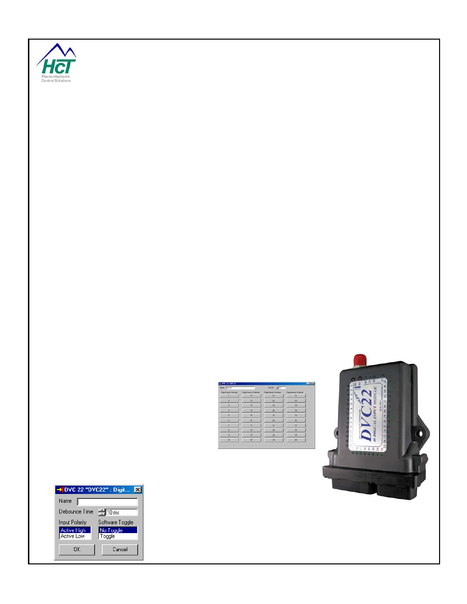
6.3 DVC22
The DVC22 screen is broken up into three
areas: Name, MAC ID, and Individual Input
Configuration. The Name is used to uniquely
identify a particular DVC expansion module.
The MAC ID tells the DVC10 how to address
the Input Module when communicating over
the CAN Bus and must be specified and be
unique. You configure the inputs by pressing
the numbered buttons.
Digital Inputs
Digital Inputs are Boolean inputs that are either
true or false. An input is enabled when its
Name field is specified. The De-bounce Time
setting is used to filter momentary spikes on
the input. The Input Polarity determines what voltage level is interpreted as a true
or false, or which edge causes a software toggle. Software toggle changes the
state of the program variable when a rising edge or falling edge is detected on the
input.