13 output groups, Output groups – High Country Tek DVC80 User Manual
Page 38
P/N: 021-00154, Rev. A.6 - updated for V4.7 Tools
Page | 38
Pulse Time Out
The amount of time elapsing without detecting a pulse before turning RPM to 0
Range: 0 to 2.0 seconds
Count Limits
Min: 0 to 65535
Max:
0 to 65535
Universal Input Code Sample
Code Comments
If (Uni_1 > 5%) Then
Test to see If Input % is greater then 5%
PWM_1 = Uni_1
Sets an PWM% output to the Analog Input %
PWM_1.Dir = Uni_1.Dir
Set direction of a dual coil based Input (if center enabled)
If( Uni_1.MaxF) then
Test Maximum Volts threshold reached ever
If (Uni_1.MaxRF) then
Test Reference Maximum volts threshold reached ever
Uni_1.MaxRF = 0
Clear /Reset condition-flag (to retry)
If (Uni_1.RealRPM > 500) then
Test Actual RPM > 500 RPM
Uni_1.MaxVolt = Uni_1.RawVolts
Set voltage max to volts seen (Calibration Example)
If (Uni_1.LOS) then
Test loss of signal (pulse input only)
Uni_1.Counter = 512
Set counter to value (counter or Quadrature type only)
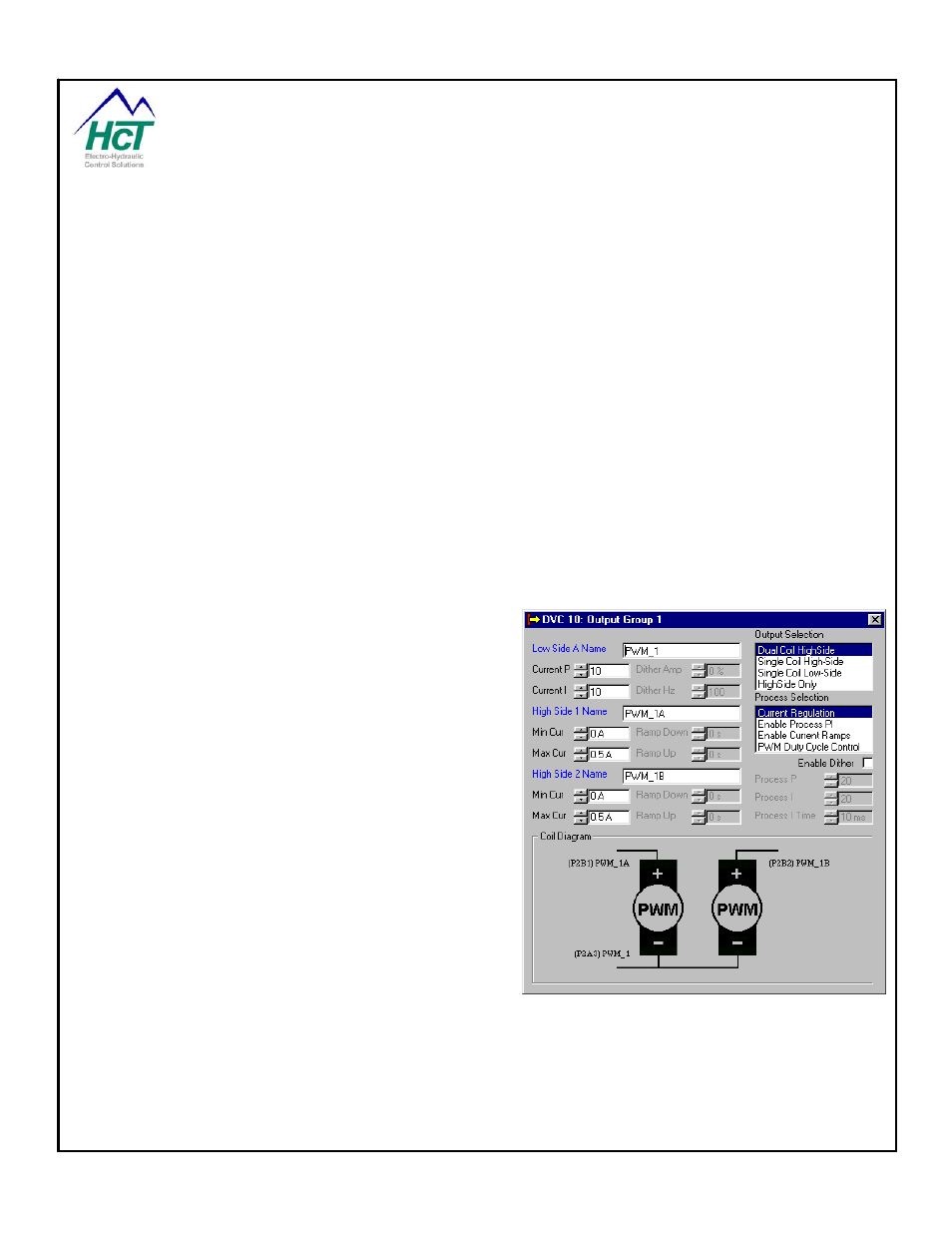
3.13 Output
Groups
The three DVC5/7/10 Output Groups are used to
configure and control valves. Each group has 2
programmable voltage source output pins (High-Side)
and one output (2 Low-Side current sensing and sinking)
pin. The DVC5 and 7 have only two low-side pins. This
pin is thought of as an output even though it receives
current and measures it. This is because the Low-side
pin using circuits internal to the DVC module also
controls the amount of time (duty cycle) the current
sinking mode is active by the application setting the
output PWM% (Pulse Width Modulated) variable. The
PWM% represents the effective High Side coil voltage.
This voltage will equal the PWM% times the system
voltage. The switch control shown in the diagram below
is the output PWM circuit.
The DVC5/7/10 controllers can control two kinds of
valves. The first type is Bang-bang valves or quick
opening valves that are fully on or off. The second type
is Proportional valves (PWM% controlled) that are
controlled by continuously measuring the received coil
current and comparing the value to a desired value and adjusting the PWM% up or down to correct the error.
The output groups are designed to give the user a great deal of flexibility. The software gives the user the ability
to control the voltage (High-Side) to the positive side of the coil and control the PWM current sinking capability
(PWM OUT) from the negative side of the coil.
Refer to the Appendices for a more in depth discussion of PWM, Dither and the PID technique used to regulate
coil current.
HIGH-SIDE OUTPUTS (HS OUT) – Qty (6 for DVC5/7/10)