14 input output functions, Input output functions – High Country Tek DVC80 User Manual
Page 45
P/N: 021-00154, Rev. A.6 - updated for V4.7 Tools
Page | 45
PWM_1.Enable Set it to TRUE (>0) to activate the valve controls for
the High Side 1 connected valve.
PWM_1 Set it to 0-1023 or 0 to 100% to cause current to flow in HS_1’s coil
HS_2 Set it to TRUE to activate the Bang-Bang valve.
Hidden Code
HS_1 = PWM_1.Enable
Single Coil Low Side
PWM_1.Enable Set it to TRUE (>0) to activate the low side valve controls.
PWM_1 Set it to 0-1023 or 0 to 100% to cause current to flow in the coil.
HS_1
Set it to TRUE to activate the Bang-Bang valve.
HS_2
Set it to TRUE to activate the Bang-Bang valve.
No Hidden Code
High-Side Only
HS_1
Set it to TRUE to activate the Bang-Bang valve
HS_2
Set it to TRUE to activate the Bang-Bang valve
No Hidden Code
PWM Frequency
PWM_1.Dir
Set to coil direction for Dual coil configuration
PWM_1.Enable Set it to TRUE (>0) to activate the low side valve controls
PWM_1.Frequency Set it to values 0 to 1000 representing 0 to100 hertz in tenth hertz
Increments
PWM_1.dutycycle Set it to values 0 to 1023 representing 0 to 100% duty cycle
PWM_1.freqerror 1 means frequency = 0 or > 1000 and 2 means dutycycle > 1023.
Open Detection
When using a PWM output to drive a ‘bang bang’ valve, be sure to set the max current in the output group to the
max current for the valve. The current feedback from the PWM output looks at the current. If the output is set to
2A, but the valve only uses 1.2A, then the controller sets the ‘open’ indicator and stops driving current.
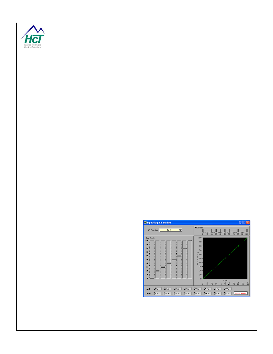
3.14
Input Output Functions
Input Output functions change the response of inputs
that are based on 0 to 100%. This function is a one
to one function, meaning that every input has exactly
one output. Input Output functions are useful in
applications where the output is not linear to the input.
These functions can be used to ramp motors with
acceleration and deceleration if the function is shaped
as a parabola. They are also useful if the output
levels are not known. The user can use the "Program
Loader Monitor" to adjust the output levels to control
the system correctly.
The DVC’s BIOS calculates the output value for a
given input value. This takes one execution cycle
typically 10ms to complete. The result of this is that
the actual output value is delayed one execution cycle
from setting the input. In other words, once you set an input value the output value will be unchanged until the
code setting the input is executed again or the next logic sequence is executed.
Note: The DVC5/7/10 BIOS software does linear interpolation between consecutive output values for a specific
input value.