Serial communications wiring, User inputs, Input a and input/user b – Red Lion C48C User Manual
Page 14: Output wiring
Serial Communications Wiring
It is recommended that shielded (screened) cable be used for serial
communications. This unit meets the EMC specifications using Alpha #2404
cable or equivalent. There are higher grades of shielded cable, such as four
conductor twisted pair, that offer an even higher degree of noise immunity.
Refer to RS-485 Serial Communications, page 30, for wiring and operational
procedures.
User Inputs
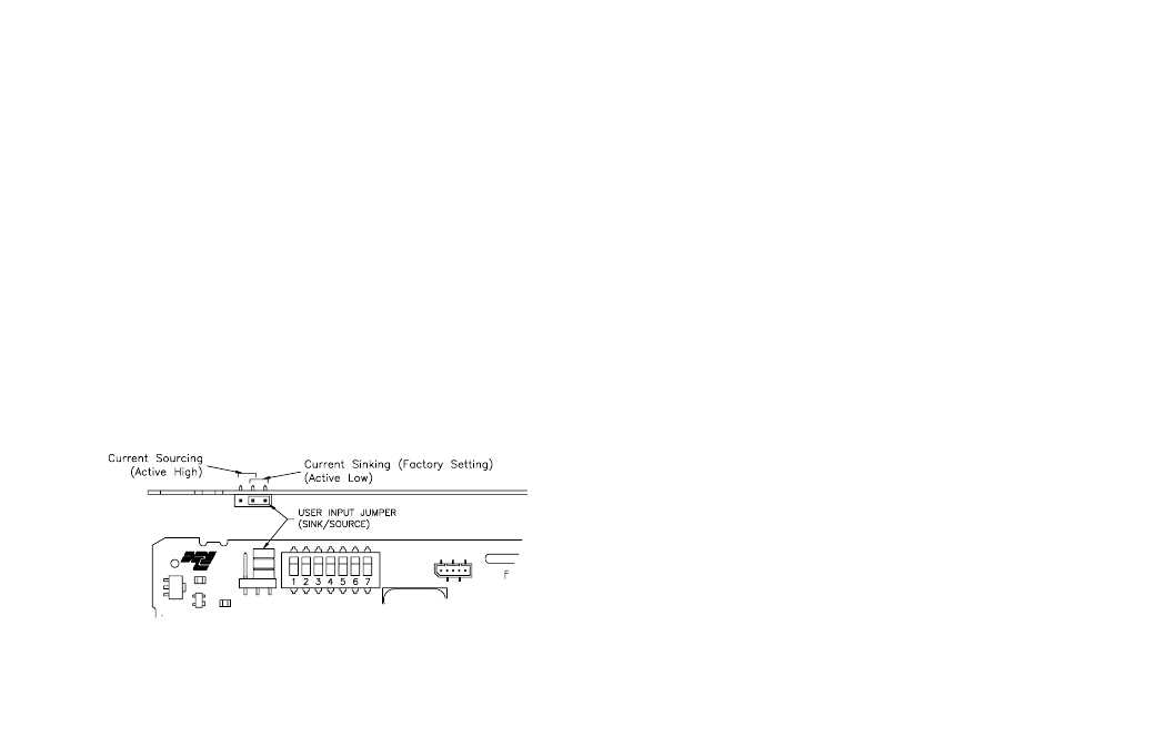
The external user inputs are programmable inputs that can be configured as
current sinking (active low) or current sourcing (active high) inputs via a single
plug jumper. Programmable external user inputs are digital inputs. The use of
shielded cable is recommended. Follow the EMC Installation Guidelines for
shield connection. The active logic state of ALL user inputs is dictated by the
position of the User Input plug jumper. The plug jumper is located on the CPU
board to the left of the DIP switches (See Figure 7, User Input Jumper
Location). Input/User B can be programmed to be a user input when only
unidirectional counting is required (See CNT IN parameter, page 17). When
programmed as a User Input, Input B’s active logic level is also controlled by
the User SNK/SRC plug jumper.
OUTPUT WIRING
Relay Connections
To prolong contact life and suppress electrical noise interference due to the
switching of inductive loads, it is good installation practice to install a snubber
across the contactor. Follow the manufacturer’s instructions for installation.
Note: Snubber leakage current can cause some electro-mechanical devices to be
held ON.
Input A and Input/User B
Input A and Input B have identical circuitry and share the same “COMM.”
terminal. Each input has separate DIP switches that configure the circuitry to
accept various types of sensor outputs.
The input schematic shows the details of the input circuitry. Each input has
three DIP switches whose functions are listed below.
To access the DIP switches, the unit assembly must be removed from the
case. See Removing The Unit Assembly, page 4, for instructions.
INPUT A
SW1 - SNK: Provides a 7.8 K
Ω
internal pull-up resistor for sensors with
current sinking outputs.
SRC: Provides a 3.9K
Ω
internal pull-down resistor for sensors with
current sourcing outputs.
SW2 - HI FRQ: Removes damping capacitor and allows operation up to the
maximum input frequency.
LO FRQ: Connects damping capacitor for switch contact debounce.
Limits count speed to 50 Hz maximum and count pulse ON or OFF
times to 10 msec. minimum.
Note:The HI/LO FRQ selection switch must be set on “LO FRQ” when switch
contacts are used to generate count input signals. The “LO FRQ” mode also
provides very high immunity against electrical noise pickup. It is
recommended that this mode also be used, whenever possible, with electronic
sensor outputs. The “LO FRQ” mode can be used with any type of sensor
output, provided count pulse widths never decrease below 10 msec, and the
count rate does not exceed 50 Hz.
-8-
Figure 7, User Input Jumper Location