HP Integrity rx4610 Server User Manual
Page 62
Chapter 6: Installing an Additional Processor
55
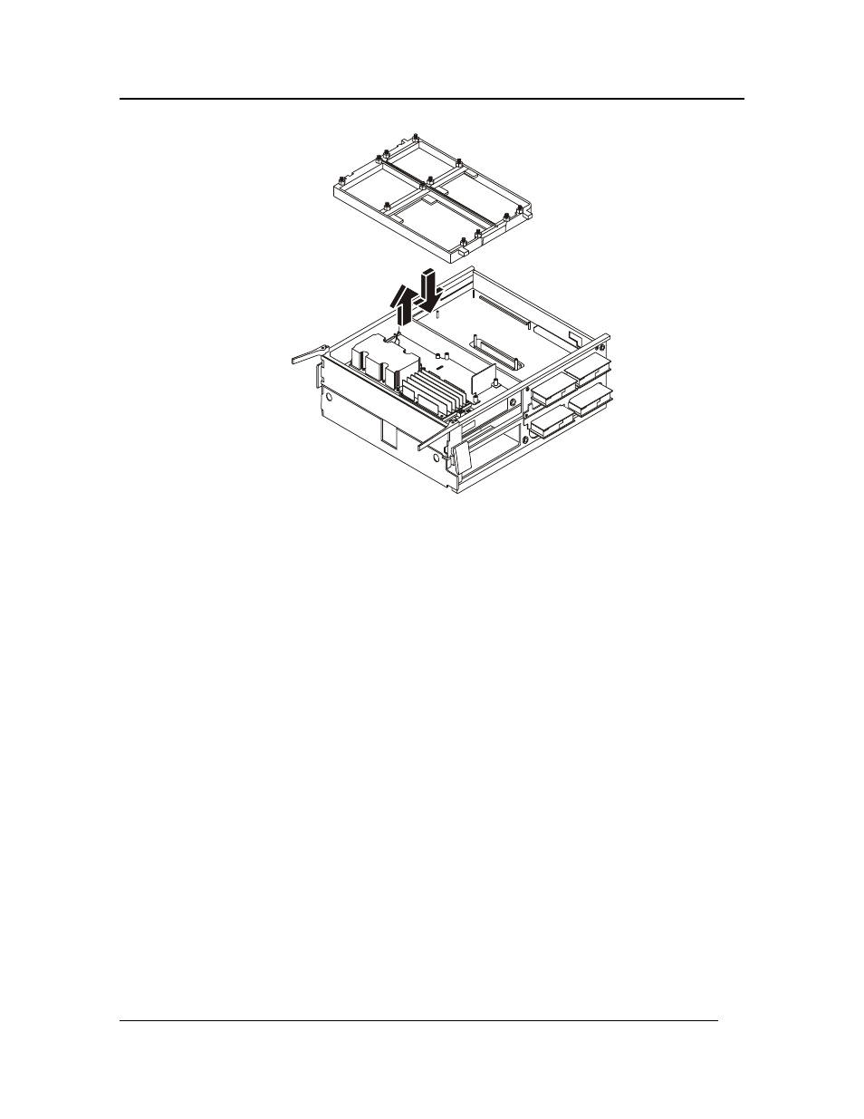
Figure 6-7. The Triple Beam
16. Install the processors and power pods into the bottom half of the Processor/Memory Complex
as described in “Installing an Additional Processor” in Chapter 6.
17. Install the triple beam and the metal baffle.
18. Install the memory board into the bottom half of the Processor/Memory Complex as described
in “Removing and Installing Memory Boards” in Chapter 5.
19. Install the Processor/Memory Complex into the server as described in “Installing the
Processor/Memory Complex” in Chapter 5.
Installing the Board in a System with Two Microprocessors
When installing a board with two microprocessors, complete the following procedure:
1. Place the bottom half of the Processor/Memory Complex on a clean ESD-protected work
surface. The bottom half has wider rails as compared to the top half. Be sure that the rail side
of the complex is in contact with the work surface.
2. Carefully place the Processor Baseboard topside up into position on the bottom half of the
Processor/Memory Complex.
3. Place the top half of the Processor/Memory Complex over the Processor Baseboard. Be sure
that the guide pin relations are correct. The Processor Baseboard should be between the two
Processor/Memory Complex halves.
4. Snap shut the four plastic latches that secure the two halves of the Processor/Memory Complex
together.
5. Tighten the two captive screws that help secure the Processor Baseboard to the
Processor/Memory Complex.
6. Carefully turn the Processor/Memory Complex over so that you can work on the underside.