Interface specifications – HP Designjet 700 Printer series User Manual
Page 195
11-7
Company confidential. Postillo/755CM User’s Guide Final Freeze Status:Frozen
This is the cyan on page 11-7 (seq: 193)
This is the black on page 11-7 (seq: 193)
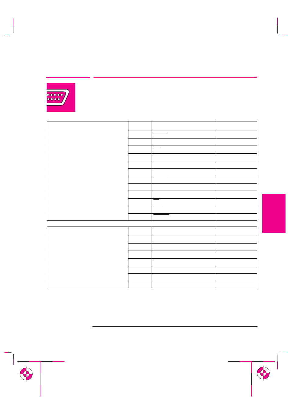
Interface Specifications
Below are the parallel and serial interface specifications. For specifications of the
HP JetDirect Network interface, see the JetDirect Print Server documentation
supplied with this printer.
Parallel (Bi-Tronics/Centronics)
Interface
Pin
Wire/Signal Name
Source
Interface
The connector on the printer is
1
Strobe
computer
The connector on the printer is
36-pin female.
2 ... 9
D0 ... D7 (data lines)
both
p
Most existing parallel cables s pport
10
Ack
printer
Most existing parallel cables support
Bi-Tronics communication, but for
11
Busy
printer
use with this printer, the cable
must
meet the specification in this table
12
PError
printer
meet the specification in this table.
13
Select (SelectOut)
printer
14
AutoFd
computer
16
GND
19 ... 30
GND
31
Init
computer
32
Fault
printer
36
SelectIn
computer
Serial (RS-232-C) Interface
Pin
Wire/Signal Name
Source
The connector on the printer is 25 pin
1
Protective Ground
The connector on the printer is 25-pin
female.
2
Transmitted Data
DTE
The printer is configured as DTE (data
3
Received Data
DCE
The rinter is configured as DTE (data
terminal equipment).
4
Request to Send
DTE
q
)
Data is transmitted on Pin 2 and
6
Data Set Ready
DCE
Data is transmitted on Pin 2 and
received on Pin 3.
7
Signal Ground
20
Data Terminal Ready
DTE
Reference
Interface Specifications
REFERENCE
11