Messages, Messages 61 – Badger Meter SRD/SRI Valve Positioners User Manual
Page 61
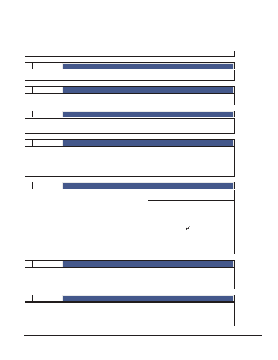
Messages
In the SRD with option “Built-in pressure sensors” flashing is superimposed by a flickering
LEDs
Description of message / LCD text
Remedy
M
1
2
3
4
¾ ¼
-
-
-
Write protected
Message 1:
write protection
Parameter and functions are write-protected
Can be changed via Configurator, PC20 / IFDC or
PC50 (FDT)-Software or Profile 3.0 (PROFIBUS)
M
1
2
3
4
¾
-
¼
-
-
Bad config CRC
Message 2:
Parameter
Invalid, undefined parameter values
Reset of configuration to factory setting in Menu
9.1
M
1
2
3
4
¾ ¼ ¼
-
-
Calib invalid
Message 3:
Calibration
Incomplete calibration or entering value resp.
calibration value outside of permissible tolerance
range
Repeat calibrations in Menus 9.2 ... 9.5
M
1
2
3
4
¾
-
-
¼
-
Ill loop current
Message 4:
Input current outside
of operating range
Check nameplate (INPUT) for correct version
Message appears at :
Analog or HART: input current under approx. 3.8
mA or above approx. 22 mA
Fieldbus or FoxCom: input current under approx.
9 mA or above approx. 12 mA
check supply voltage (Analogue) or
Bus voltage (Fieldbus),
exchange SRD if necessary
M
1
2
3
4
¾ ¼
-
¼
-
Pot problem
Message 5:
Position sensor
Position sensor input recognizes error
check 3-pole plug at electronic board
check cable to sensor
check sensor (Potentiometer: 5k +20% –0%)
Position not within permissible rotation angle range.
Lower deviation of the original 0% and exceeding
of the original 100%, which have been determined
by Autostart.
Check feedback lever mounting (flat area points to
arrow on housing)
During Autostart a change of the direction of mo-
vement was found
Acknowledge via key ( ) , then o.k.
Check further possible reasons:
valve seat worn-out; spindle lock out-of-line; carrier
unit on spindle lock is damaged (for determination of
valve position).
M
1
2
3
4
¾
-
¼ ¼
-
IP motor problem
Message 6:
I/P-converter output
Connection I/P converter to electronic board faulty check 2-pole plug at electronic board
check cable to the I/P converter
check I/P converter to detect short circuit or inter-
ruption
M
1
2
3
4
¾ ¼ ¼ ¼
-
No supply press
Message 7:
Air supply /
pneumatic error
Detection:
spring closes: w > 2 %, but position < 1 %
spring opens: w < 98 %, but position > 99 %
without spring:
no actuator change in direction of position signal
check air supply pressure
lead cable separated
possibly poor control parameters are set
pneumatic parts blocked
Page 61
Troubleshooting Guide
August 2014
POS-UM-00009-EN-02