Options, Limit switch, Additional inputs / outputs – Badger Meter SRD/SRI Valve Positioners User Manual
Page 30: Options 30, Limit switch 30 additional inputs / outputs 30
OPTIONS
Limit Switch
For detailed information, see
“Option Limit Switch” on page 58
Figure 34: Limit switch
Switch Functions
Feedback lever, feedback shaft and the control
vanes are all connected to each other, without an
intermediate transmission The control vanes are
therefore moving simultaneously with the same
angle rate as the feedback lever The length of
the control vane corresponds with the swing
angle of 120°
Both control vanes are located on different planes
Each control vane can be seen independently
from the other, because each has its own sensor
(or microswitch)
By adjusting the screws 1 and 2, the control vanes
can be adjusted relatively to the angle rate, so
that, for example, one vane dives into and another
dives out of the sensor
Testing Switch Behavior
Voltage measuring above the terminals:
vane inserted: approx 4 V
vane free:
approx 7 V
(if Ri of external supply is approx 1 kOhm)
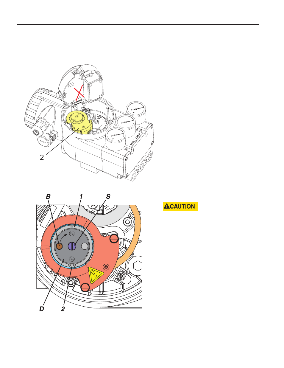
Figure 35: Setting trigger points
Setting Limit Switch Trigger Points
DO NOT TOUCH CONTROL VANES DURING
OPERATION—POSSIBILITY OF INJURIES!
First loosen screw S until disc D is no longer
blocked by bolt B Then turn disc by 90°, until set
screws 1 and 2 are accessible
Set trigger point switch GW1:
Turn screw 1 at mark (•), until desired switch
behavior is reached
Set trigger point switch GW2:
Turn screw 2 at mark (• •), until desired switch
behavior is reached
To fix switch points, turn disc again by 90° until
the bolt catches, then fasten center screw S
Additional Inputs / Outputs
All SRD versions are prepared for a subsequent conversion to this option, if not already installed at the factory
Page 30
Options
August 2014
POS-UM-00009-EN-02