Linear actuator, direct mounting, Linear actuator, direct mounting 23 – Badger Meter SRD/SRI Valve Positioners User Manual
Page 23
Linear Actuator, Direct Mounting
Actuators with appropriately prepared yoke (PA200, PA350)
enable mounting of the SRD directly to the actuator yoke
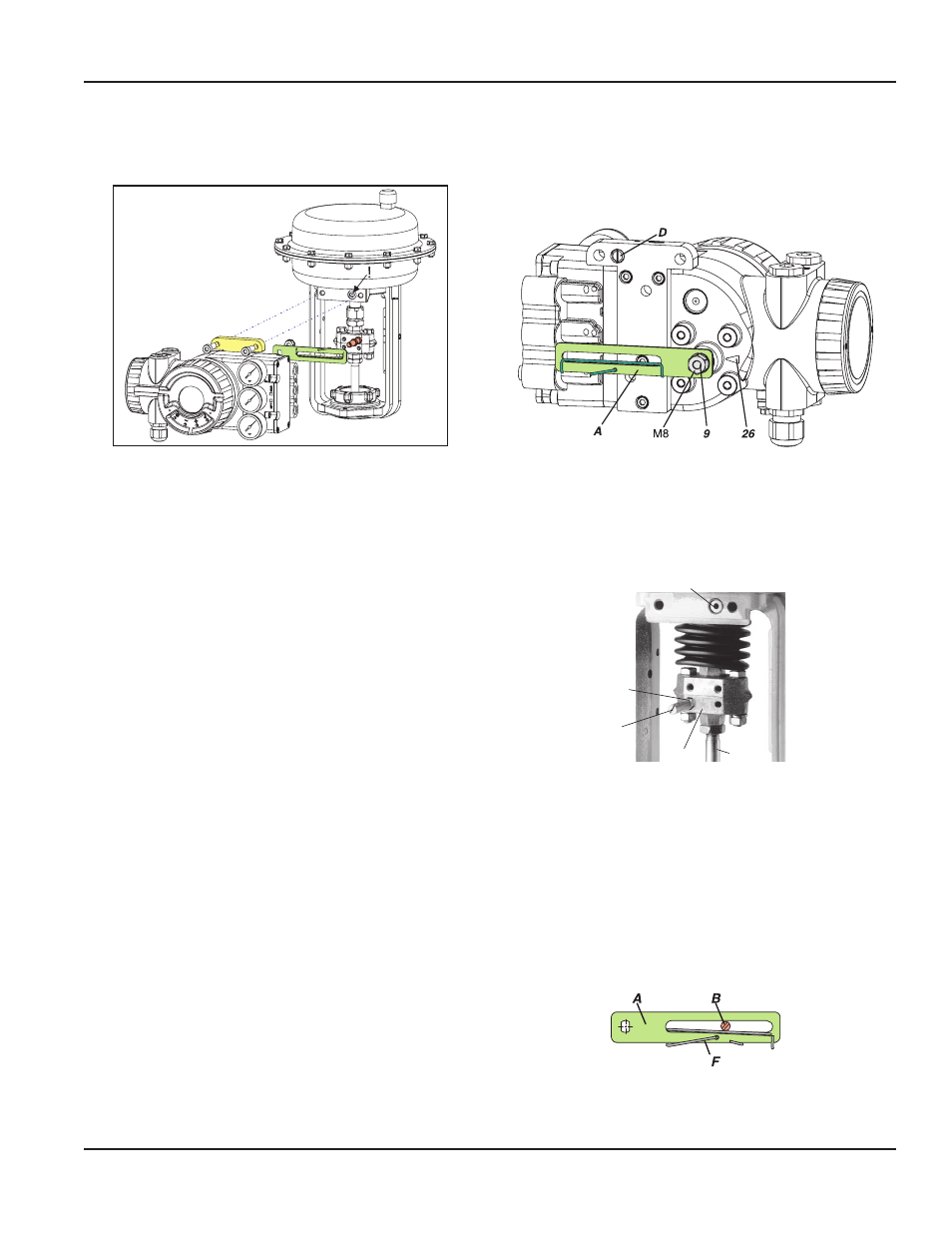
Figure 23: Direct mounting to linear actuator
The positioner is attached by bolting it directly to the
actuator yoke using the feedback lever for a direct mount
(with attachment kit EBZG -E)
The rear output I and the side outputs I and II are used
as follows:
• Actuator single acting, spring force closes:
The rear output I is used (remove lock screw in hole D)
The side output I is closed by means of a lock screw
• Actuator single acting, spring force opens:
The side output I is used
The rear output I is closed by means of a lock screw
• Actuator double acting:
The rear output I and the side output II is used
The side output I is closed by means of a lock screw
Pneumatic connections: Do not use Teflon tape for sealant
The fine fibers could disturb the function of the SRD Use only
Loctite® #243 for sealant and apply it only to male threads
Screw-type glands for electrical connections are positioned
on the lower side Any idle female threads are closed by
means of plugs
Preparation of the Positioner
Rotate the shaft stub of shaft 9 so that the flat on the shaft
stub is perpendicular to the arrow 26 on the housing (see
“Mounting Dimensions, Direct Mounting”
) Fasten the feedback
lever A to the shaft by means of spring washer and nut M8
Figure 24: Positioner preparation
Preparation of the Actuator
Screw in the carrier bolt B on the coupling piece K on the
drive spindle S at the lower left and lock it by means of a
nut M6
M6
B
K
S
R
Figure 25: Actuator preparation
Mounting of the Positioner
Fasten the positioner to the upper part of the yoke using
2 spring washers and 2 screws M8 x 80, as shown The
rear output I of positioner has contact to the air duct R in
the yoke
Attention: Note the correct position of the O-ring on the yoke
for the rear connection I!
The carrier bolt B is in the slot of the feedback lever A and the
compensating spring F touches the carrier bolt
Figure 26: Feedback lever
Page 23
Mounting to Linear Actuators
August 2014
POS-UM-00009-EN-02