Badger Meter SRD/SRI Valve Positioners User Manual
Page 53
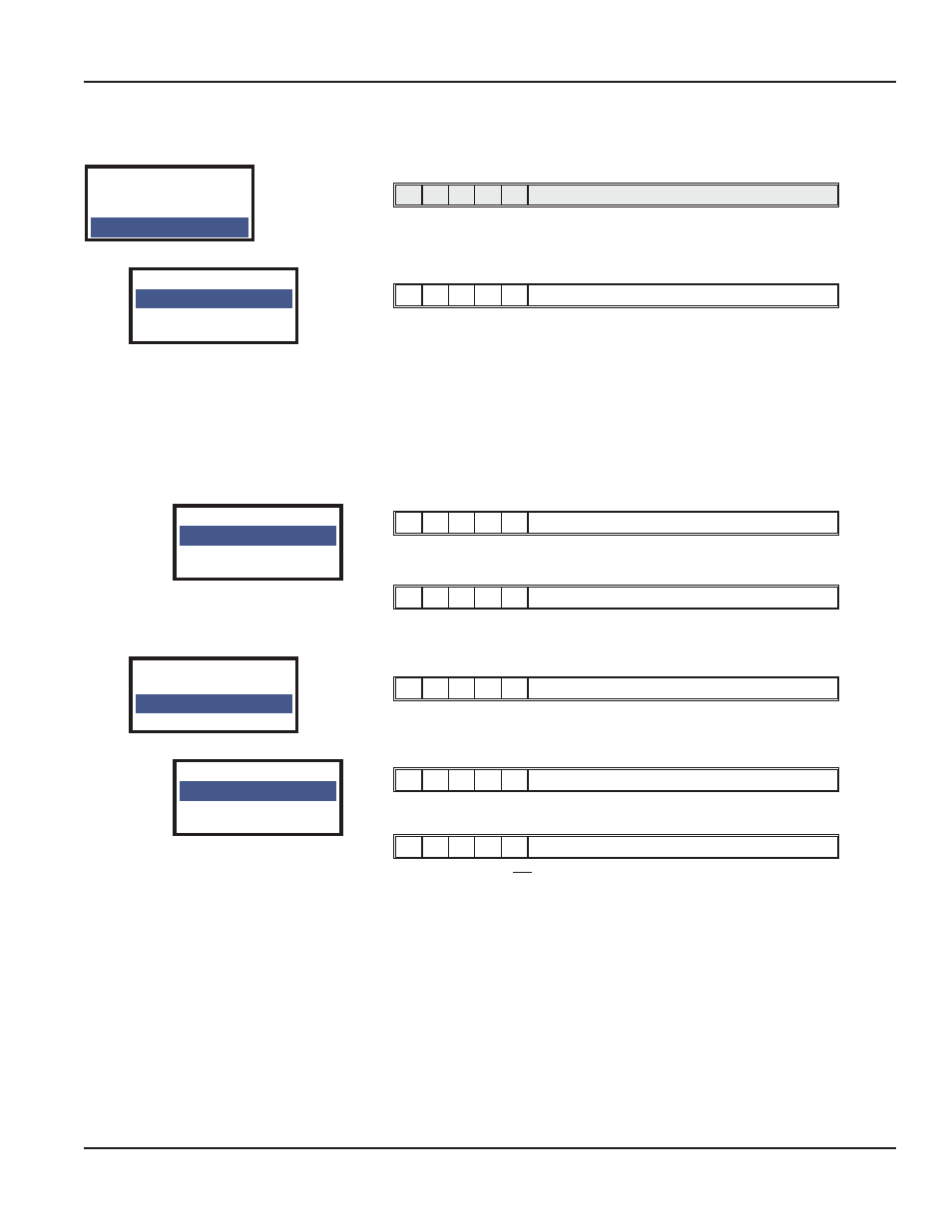
SRD960 with FOUNDATION Fieldbus:
Menu 10: FF Configuration
M
1
2
3
4
½
-
-
½ ½
M, LED 3 and LED 4 flash
Special settings for Foundation Fieldbus device.
10.1 Simulate enable / disable
¼ ¾
-
-
-
M short flash, LED 1 long flash
The SRD960 sends during normal operation its actual Position-Actual-
Value
1)
back to the control system.
If, however, “Simulate” is released in the SRD and in addition via communi-
cation Simulate is activated, then a simulation value coming from the control
system is sent back as an actual value to the control system. In this way
within the control system, e.g. the reaction to specific valve adjustments can
be tested without having to adjust the valve – the SRD regulates toward the
”accurate” setpoint value.
For further information about the Simulate see TI EVE0105 Q.
10.1.1 Simulate Disabled
-
1
-
-
-
LED 1 lights up
Disable simulate. The real valve position will be indicated.
10.1.2 Simulate Enabled
-
-
-
-
1
LED 4 lights up
Release simulate.
10.2 Foundation Fieldbus Profile: Activate Link Master
¼
-
¾
-
-
M short flash, LED 2 long flash
10.2.1 Link Master active
-
1
-
-
-
LED 1 lights up
This SRD becomes the Link Master if Control System is down.
10.2.2 Basic device
-
-
-
-
1
LED 4 lights up
This SRD becomes not the Link Master if Control System is down.
By using the UP or DOWN keys the desired condition can be selected and
entered through pressing keys UP+DOWN.
1)
With the option ”Position Feedback”, the position-actual-value will be displayed, as before,
as analog value 4 to 20 mA.
SRD Main Menu
8 Setpoint
9 Workbench
10 FF Config
10 FF Config
10.1 Simulate
10.2 Profile
10.1 Simulate
10.1.1 Disabled
10.1.2 Enabled
10 FF Config
10.1 Simulate
10.2 Profile
10.2 Profil
10.2.1 Link Mast
10.1.2 Basic Dev
Page 53
Startup
August 2014
POS-UM-00009-EN-02