Mounting to rotary actuators, Mounting to rotary actuators 25 – Badger Meter SRD/SRI Valve Positioners User Manual
Page 25
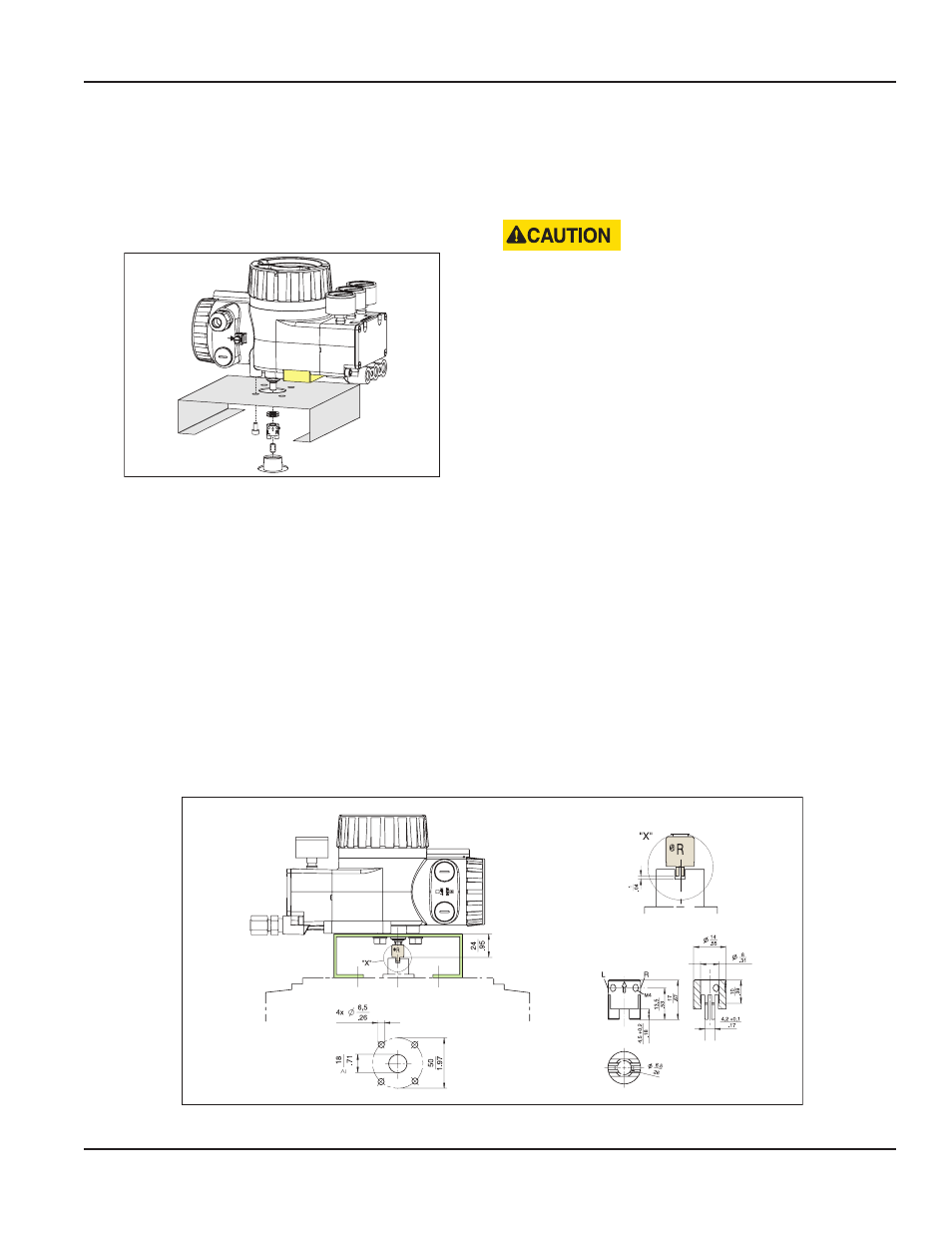
Mounting to Rotary Actuators
Applicable to rotary actuators that meet the VDI/VDE 3845
standard for mounting Installation position of positioner:
Mount the positioner so that the pneumatic connections
are in the same direction as the longitudinal drive axis of the
actuator as shown in
Figure 28: Mounting to rotary actuator
MPORTANT
I
The feedback shaft 9 of the SRD has no mechanical stop,
therefore, it may spin around. The permissible rotation angle
range is between +50 and –50 degrees around the arrow at
the housing concerning the flat area of the feedback shaft
“Mounting Dimensions, Direct Mounting”
). Since a rotary
actuator has a rotary angle of about 90 degrees, the mounting
the following mounting procedure must be followed.
Attach the positioner to the actuator using the rotary
adaptor kit EBZG -R
Either of the side outputs I (or I and II) is used and the rear
output I is closed by means of the lock screw 522 588 013
Pneumatic connections: Do not use Teflon tape for sealant
The fine fibers could disturb the function of the SRD Use only
Loctite® #243 for sealant and apply it only to male threads
Screw-type glands for electrical connections are used as
needed Any unused threaded holes are closed by plugs
PREVENT ACCUMULATION OF WATER IN THE
INSTRUMENT IN THIS MOUNTING POSITION BY SEALING
CABLE ENTRY AGAINST WATER. PROVIDE A CONTINUOUS
SUPPLY OF DRY INSTRUMENT AIR.
Preparation of Positioner
Valve must be in a failsafe position and the direction of
rotation of the actuator drive shaft must be known These
items are extremely important for proper functioning These
items can be checked as follows in case they are not clear:
• In the single-acting actuator the force of the installed
springs closes The pressureless actuator is in failsafe
position Through manually feeding compressed air it can
be seen whether the actuator drive shaft rotates to the
left or to the right In the powerless SRD is y1 pressureless
• In the double-acting actuator without spring reset both
air chambers are basically equal Failsafe position can be
either “open” or “close” Therefore, indication of the failsafe
position has to be determined by engineering Then
the direction of rotation may be determined by manual
feeding of compressed air In the powerless SRD is y1
pressureless and y2 under pressure
Bolt 2 is screwed into actuator drive shaft 1 for subsequent
centering of the rotary adaptor 3 The attachment console is
mounted to the stroke actuator (see
and
)
Figure 29: Attachment diagram for bracket
Page 25
Mounting to Linear Actuators
August 2014
POS-UM-00009-EN-02