Badger Meter SRD/SRI Valve Positioners User Manual
Page 46
Menu 6: Parameter for Position Controller
Along with the determination of the actuator geometry and control
parameters the suitable setting parameters for the position controller are
determined via function AUTO- START in Menu 2. Assessment of a
control behavior generally is very subjective. Partially a quick response is
requested without consideration of the overshoot width, partially a very
smooth swinging is requested with minor overshoot.
We basically recommend to first perform the execution of the automatic
setting via AUTOSTART in Menu 2 in order to achieve a stable control
behavior. Corrections may then be made from the determined values.
In rare cases AUTOSTART cannot find the optimal setting for the
respective application. See “Remarks for controller optimization” following
table 4.
For small actuators an improvement of the control behavior can be achie-
ved also by increasing damping at the pneumatic output. A further
optimization may follow by repeating AUTOSTART.
M
1
2
3
4
½ ½
-
½
-
M, LED 1 and LED 3 flash
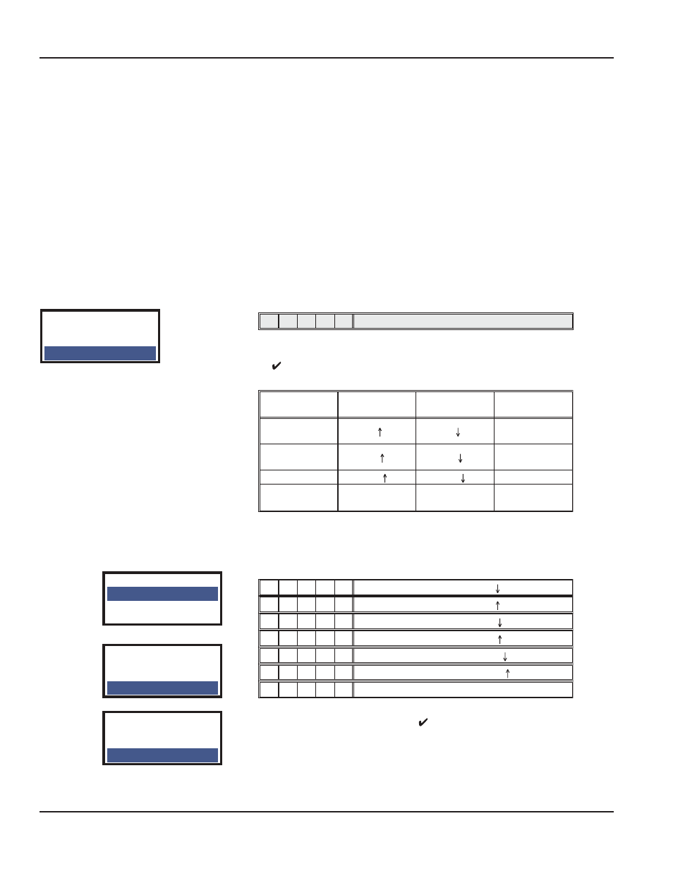
Seven control parameters are combined in Menu 6 each availing of a sub-
menu. 15 different values may be selected in each of these and pressing
of ( ) be entered in the position controller as constant. Controller type is a
PI controller.
Parameter-
Designation
Valve is
opening
Valve is
closing
Unit
Proportionate
amplification
KP
P
P
-
Integration time
constant
Tn
Tn
sec
Positioning time
T63
T63
sec
Dead band for
control diff.
GAP
GAP
% of span
The dead band prevents (at the expense of accuracy) that the valve in the
controlled condition constantly moves around the setpoint. This less harms
the mechanical parts of the actuator and in particular the valve packing.
Selection of sub-menus:
M
1
2
3
4
¼
-
¾
-
-
M, LED 2 flash:
P
¼ ¾ ¾
-
-
M, LED 1 and LED 2 flash:
P
¼
-
-
¾
-
M, LED 3 flash:
Tn
¼ ¾
-
¾
-
M, LED 1 and LED 3 flash:
Tn
¼
-
-
-
¾
M, LED 4 flash:
T63
¼ ¾
-
-
¾
M, LED 1 and LED 4 flash:
T63
¼
-
¾ ¾
-
M, LED 2 and LED 3 flash:
GAP
Following selection of the sub-menu the codes for the parameter values
(table 4) can be selected by pressing ( ) :
SRD Main Menu
4 Valve Char.
5 Limits/Alarms
6 Parameters
6 Parameters
6.1 Gain closing
6.2 Gain opening
6.3 Res time cl
etc.
6 Parameters
6.4 Res time op
6.5 Rate lim cl
6.6 Rate lim op
6 Parameters
6.5 Rate lim cl
6.6 Rate lim op
6.7 Control gap
Page 46
Startup
August 2014
POS-UM-00009-EN-02