Block diagram, Operation, Block diagram 13 operation 13 – Badger Meter SRD/SRI Valve Positioners User Manual
Page 13
Block Diagram
x
Position
of actuator
y
1
Output
pressure
y
2
to actuator
Input (w) each
acc. to version:
•
Analog operation
4...20 mA
(+FSK)
•
Digital operation
FSK
13...36 V DC
•
Bus input
s Air supply 1.4 ... 6 bar (20 ... 90 psig)
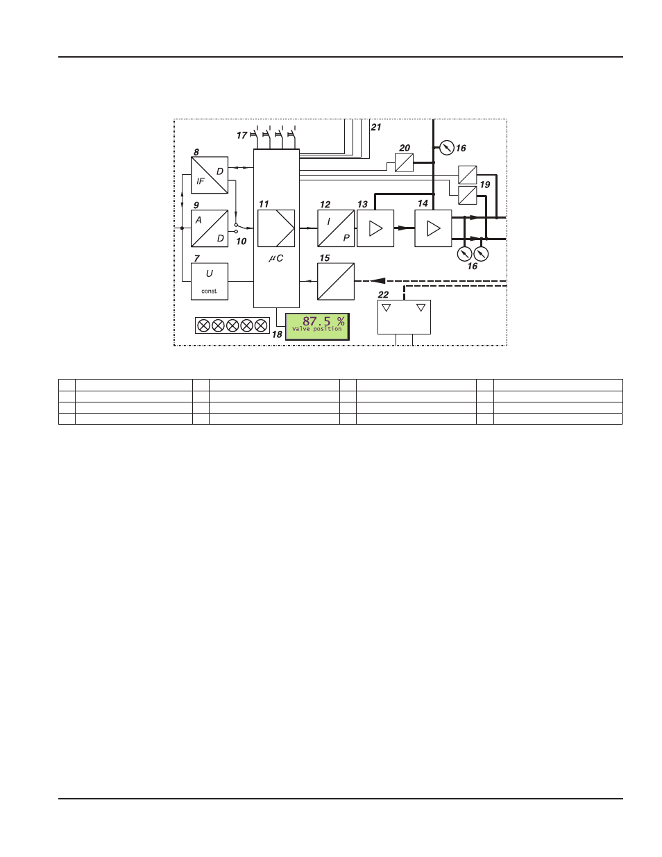
Figure 7: Block diagram
7 Voltage Converter
11 Digital Controller
15 Position Sensor
19 Pressure Sensor
8 Interface Component
12 IP Module
16 Optional Gauges
20 Pressure Sensor
9 A/D Transformer
13 Pre-Amplifier
17 Local Keys
21 Outputs
10 Switch
14 Pneumatic Power Amplifier
18 LCDs
22 Optional Mechanical Limit Switch
Operation
With the universal positioner with input signal 4…20 mA or superimposed HART signal, the supply takes place via the power
signal adjacent to the input
By means of voltage converter 7, derivation of the internal supply of the electronic takes place The power value is measured,
in A/D transformer 9 converted, and directed via switch 10 to digital controller 11
With PROFIBUS-PA or FOUNDATION Fieldbus, the SRD is powered by means of the bus lead The positioner is operated
from a control system by sending a setpoint (setpoint value) to the positioner The digital signal is directed via the interface
component 8 to the digital controller 11 By means of the voltage converter 7 the internal supply of the electronic is
established, fed via the bus lead
With FoxCom digital operation, a DC voltage is provided at input w On this voltage a FSK-signal is modulated The modulation
contains information (such as setpoint value), sent digitally to the control unit 11 across the FSK-unit 8
The output of controller 11 drives the electro-pneumatic converter (IP-module) 12, controlling a pre-amplifier 13, the
single acting (or double acting) pneumatic power amplifier 14 The output of the amplifier 14 is the output pressure y to
the actuator
The pneumatic amplifiers are supplied with supply air s 1 4…6 bar (20…90 psig)
The position x of the actuator is sent to the control unit 11 by the position sensor (conductive plastic potentiometer) 15
Optional gauges 16, pressure sensors 19, 20, inputs / outputs 21 (two binary outputs; a 4…20 mA output and alarm;
control inputs for ‘Open/Close’ and ‘Hold last value’) enable additional diagnostic indications and possible intervention The
mechanical limit switch 22 (optional) enables independent alarm signals
Adjusting, startup of the positioner, and the demand for internal information can be made using the local keys 17 with
indication given by LCDs 18 or LEDs
Page 13
Method of Operation
August 2014
POS-UM-00009-EN-02