Functional designations, Functional designations 15 – Badger Meter SRD/SRI Valve Positioners User Manual
Page 15
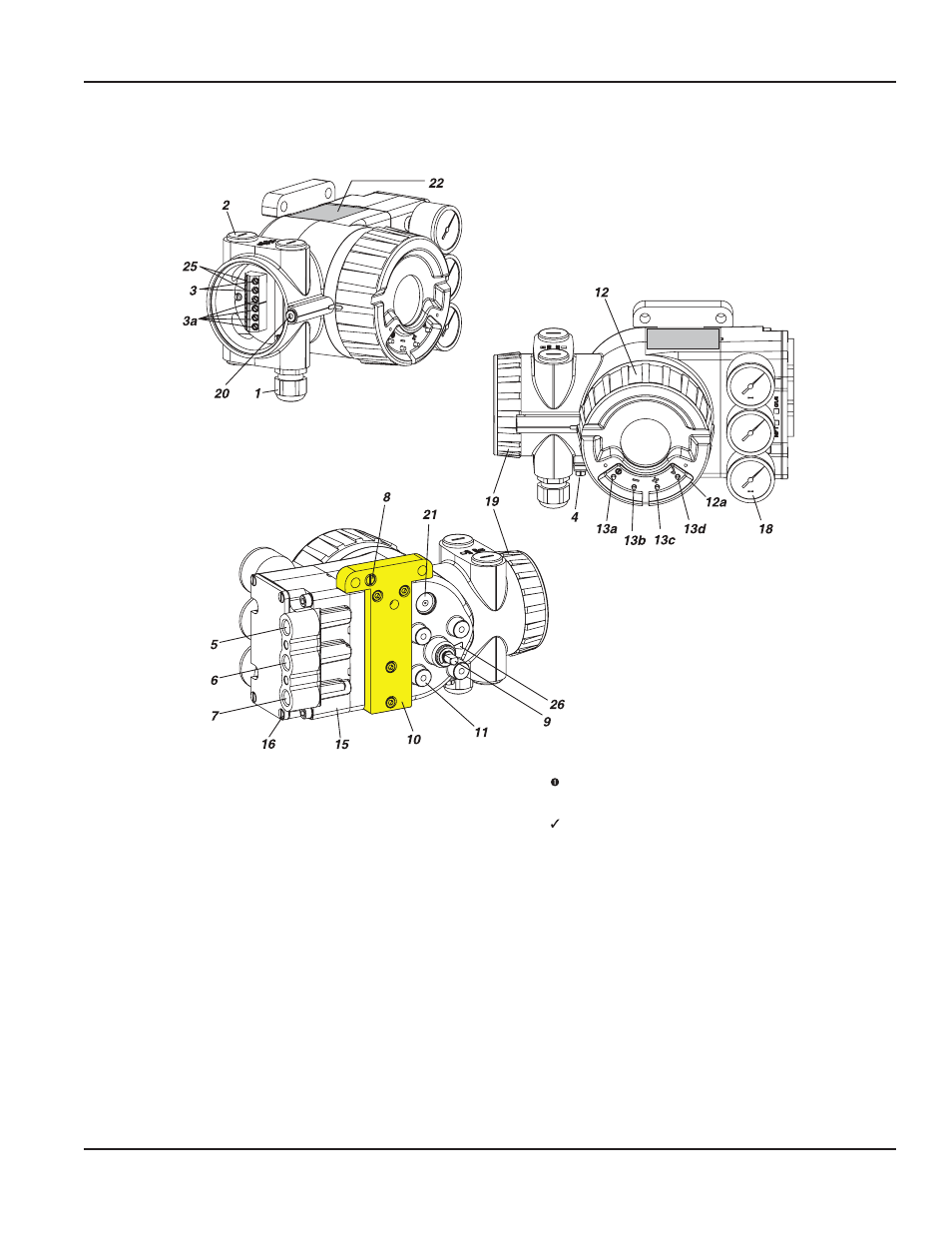
FUNCTIONAL DESIGNATIONS
1
Cable gland
1)
2
Plug
1)
, interchangeable by Pos
1
3
Screw terminals
2)
(11 +/12 –) for input (w)
or (11 / 12) for Bus connection acc. IEC 1158-2
3a Screw terminals
2)
for additional inputs / outputs
4
Ground connection
5
Female thread G ¼ or ¼-18 NPT
3)
for output I (y1)
6
Female thread G ¼ or ¼-18 NPT
3)
for air supply (s)
7
Female thread G ¼ or ¼-18 NPT
3)
for output II (y2)
8
Direct connection for output I (y1-d)
9
Feedback shaft
10 Connection manifold for attachment to stroke actuators
11 Connection base for attachment to rotary actuators
12 Cover with window and external push buttons
12a Push button protection cover (option -X) (not shown)
1)
Cable glands BUSG.
The device is supplied with dust protection covers
2)
optional: Cage clamps (WAGO)
3)
Type of thread is marked at housing.
13a Key
MENU
13b Key – DOWN
13c Key + UP
13d Key
ENTER / STORE
15 pneumatic unit with amplifier and connection
16 4 screws for connection of pneumatic unit
18 built-in pressure gauges for air-supply, output
Y1 and output Y2
19 Cover for electronic connection compartment
20 Protection screw for electronic connection and
electronic compartment
21 Air vent, dust and water protected,
(IP65 and NEMA 4X)
22 Data label
22a Label for Options
25 Tip jacks, 2 mm dia. (integrated in Terminals)
26 Arrow is perpendicular to shaft 9 at angle 0 degree
Figure 8: Functional designations
Page 15
Functional Designations
August 2014
POS-UM-00009-EN-02